
This is a replacement for a Milight/LimitlessLED remote/gateway hosted on an ESP8266. Leverages Henryk Plötz's awesome reverse-engineering work.
Milight bulbs are cheap smart bulbs that are controllable with an undocumented 2.4 GHz protocol. In order to control them, you either need a remote ($13), which allows you to control them directly, or a WiFi gateway ($30), which allows you to control them with a mobile app or a UDP protocol.
This project is a replacement for the wifi gateway.
This guide on my blog details setting one of these up.
- Both the remote and the WiFi gateway are limited to four groups. This means if you want to control more than four groups of bulbs, you need another remote or another gateway. This project allows you to control 262,144 groups (4*2^16, the limit imposed by the protocol).
- This project exposes a nice REST API to control your bulbs.
- You can secure the ESP8266 with a username/password, which is more than you can say for the Milight gateway! (The 2.4 GHz protocol is still totally insecure, so this doesn't accomplish much :).
- Official hubs connect to remote servers to enable WAN access, and this behavior is not disableable.
- This project is capable of passively listening for Milight packets sent from other devices (like remotes). It can publish data from intercepted packets to MQTT. This could, for example, allow the use of Milight remotes while keeping your home automation platform's state in sync. See the MQTT section for more detail.
The following remotes can be emulated:
Support has been added for the following bulb types:
| Model # | Name | Compatible Bulbs |
|---|---|---|
| FUT096 | RGB/W |
|
| FUT005, FUT006,FUT007 | CCT |
|
| FUT098 | RGB | Most RGB LED Strip Controlers |
| FUT092 | RGB/CCT |
|
| FUT091 | CCT v2 | Most newer dual white bulbs and controllers |
| FUT089 | 8-zone RGB/CCT | Most newer rgb + dual white bulbs and controllers |
Other remotes or bulbs, but have not been tested.
- An ESP8266. I used a NodeMCU.
- A NRF24L01+ module (~$3 on ebay). Alternatively, you can use a LT8900.
- Some way to connect the two (7 female/female dupont cables is probably easiest).
This project is compatible with both NRF24L01 and LT8900 radios. LT8900 is the same model used in the official MiLight devices. NRF24s are a very common 2.4 GHz radio device, but require software emulation of the LT8900's packet structure. As such, the LT8900 is more performant.
Both modules are SPI devices and should be connected to the standard SPI pins on the ESP8266.
This guide details how to connect an NRF24 to an ESP8266. By default GPIO 4 for CE and GPIO 15 for CSN are used, but these can be configured late in the Web GUI under Settings -> Setup.


| NodeMCU | Radio | Color |
|---|---|---|
| GND | GND | Black |
| 3V3 | VCC | Red |
| D2 (GPIO4) | CE | Orange |
| D8 (GPIO15) | CSN/CS | Yellow |
| D5 (GPIO14) | SCK | Green |
| D7 (GPIO13) | MOSI | Blue |
| D6 (GPIO12) | MISO | Violet |
Image source: MySensors.org
Connect SPI pins (CE, SCK, MOSI, MISO) to appropriate SPI pins on the ESP8266. With default settings, connect RST to GPIO 0, PKT to GPIO 16, CE to GPIO 4, and CSN to GPIO 15. Make sure to properly configure these if using non-default pinouts.
The goal here is to flash your ESP with the firmware. It's really easy to do this with PlatformIO:
export ESP_BOARD=nodemcuv2
platformio run -e $ESP_BOARD --target upload
Of course make sure to substitute nodemcuv2 with the board that you're using.
You can find pre-compiled firmware images on the releases.
This project uses WiFiManager to avoid the need to hardcode AP credentials in the firmware.
When the ESP powers on, you should be able to see a network named "ESPXXXXX", with XXXXX being an identifier for your ESP. Connect to this AP and a window should pop up prompting you to enter WiFi credentials. If your board has a built-in LED (or you wire up an LED), it will flash to indicate the status.
The network password is "milightHub".
Both mDNS and SSDP are supported.
- OS X - you should be able to navigate to http://milight-hub.local.
- Windows - you should see a device called "ESP8266 MiLight Gateway" show up in your network explorer.
- Linux users can install avahi (
sudo apt-get install avahi-daemonon Ubuntu), and should then be able to navigate to http://milight-hub.local.
The HTTP endpoints (shown below) will be fully functional at this point. You should also be able to navigate to http://<ip_of_esp>, or http://milight-hub.local if your client supports mDNS. The UI should look like this:
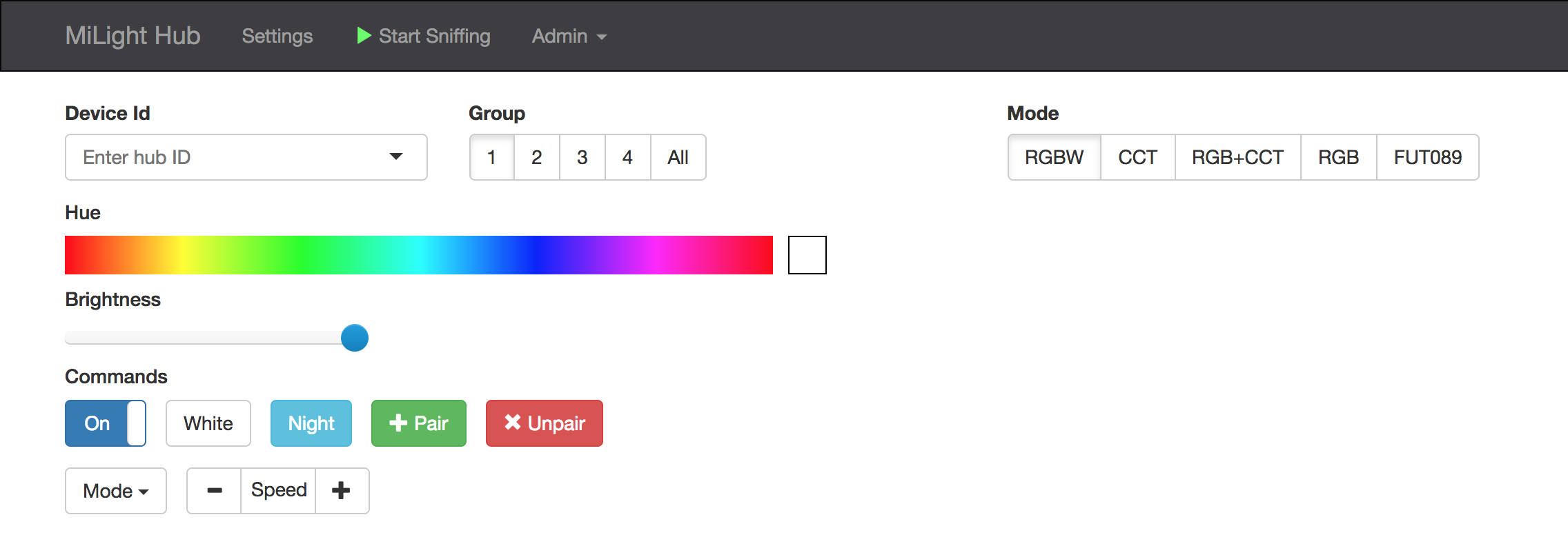
If it does not work as expected see Troubleshooting.
If you need to pair some bulbs, how to do this is described in the wiki.
Some ESP boards have a built-in LED, on pin #2. This LED will flash to indicate the current status of the hub:
- Wifi not configured: Fast flash (on/off once per second). See Configure Wifi to configure the hub.
- Wifi connected and ready: Occasional blips of light (a flicker of light every 1.5 seconds).
- Packets sending/receiving: Rapid blips of light for brief periods (three rapid flashes).
- Wifi failed to configure: Solid light.
In the setup UI, you can turn on "enable_solid_led" to change the LED behavior to:
- Wifi connected and ready: Solid LED light
- Wifi failed to configure: Light off
Note that you must restart the hub to affect the change in "enable_solid_led".
You can configure the LED pin from the web console. Note that pin means the GPIO number, not the D number ... for example, D2 is actually GPIO4 and therefore its pin 4. If you specify the pin as a negative number, it will invert the LED signal (the built-in LED on pin 2 is inverted, so the default is -2).
If you want to wire up your own LED on a pin, such as on D2/GPIO4, put a wire from D2 to one side of a 220 ohm resister. On the other side, connect it to the positive side (the longer wire) of a 3.3V LED. Then connect the negative side of the LED (the shorter wire) to ground. If you use a different voltage LED, or a high current LED, you will need to add a driver circuit.
GET /. Opens web UI.GET /about. Return information about current firmware version.POST /system. Post commands in the form{"comamnd": <command>}. Currently supports the commands:restart.POST /firmware. OTA firmware update.GET /settings. Gets current settings as JSON.PUT /settings. Patches settings (e.g., doesn't overwrite keys that aren't present). Accepts a JSON blob in the body.GET /remote_configs. Get a list of supported remote configs (akadevice_types).GET /gateway_traffic(/:device_type)?. Starts an HTTP long poll. Returns any Milight traffic it hears. Useful if you need to know what your Milight gateway/remote ID is. Since protocols for RGBW/CCT are different, specify one ofrgbw,cct, orrgb_cctas:device_type. The path/gateway_trafficwithout a:device_type` will sniff for all protocols simultaneously.PUT /gateways/:device_id/:device_type/:group_id. Controls or sends commands to:group_idfrom:device_id. Accepts a JSON blob. The schema is documented below in the Bulb commands section.GET /gateways/:device_id/:device_type/:group_id. Returns a JSON blob describing the state of the the provided group.POST /raw_commands/:device_type. Sends a raw RF packet with radio configs associated with:device_type. Example body:{"packet": "01 02 03 04 05 06 07 08 09", "num_repeats": 10}
Route (5) supports these commands. Note that each bulb type has support for a different subset of these commands:
status. Toggles on/off. Can be "on", "off", "true", or "false".hue. Sets color. Should be in the range[0, 359].saturation. Controls saturation.level. Controls brightness. Should be in the range[0, 100].temperature. Controls white temperature. Should be in the range[0, 100].mode. Sets "disco mode" setting to the specified value. Note that not all bulbs that have modes support this command. Some will only allow you to cycle through next/previous modes using commands.command. Sends a command to the group. Can be one of:set_white. Turns off RGB and enters WW/CW mode.pair. Emulates the pairing process. Send this command right as you connect an unpaired bulb and it will pair with the device ID being used.unpair. Emulates the unpairing process. Send as you connect a paired bulb to have it disassociate with the device ID being used.next_mode. Cycles to the next "disco mode".previous_mode. Cycles to the previous disco mode.mode_speed_up.mode_speed_down.level_down. Turns down the brightness. Not all dimmable bulbs support this command.level_up. Turns down the brightness. Not all dimmable bulbs support this command.temperature_down. Turns down the white temperature. Not all bulbs with adjustable white temperature support this command.temperature_up. Turns up the white temperature. Not all bulbs with adjustable white temperature support this command.night_mode. Enable "night mode", which is minimum brightness and bulbs only responding to on/off commands.
commands. An array containing any number of the above commands (including repeats).
The following redundant commands are supported for the sake of compatibility with HomeAssistant's mqtt light platform with the json schema:
color. Hash containing RGB color. All keys for r, g, and b should be present. For example,{"r":255,"g":200,"b":255}.color_temp. Controls white temperature. Value is in mireds. Milight bulbs are in the range 153-370 mireds (2700K-6500K).brightness. Same aslevelwith a range of[0,255].state. Same asstatus.
If you'd like to control bulbs in all groups paired with a particular device ID, set :group_id to 0.
Turn on group 2 for device ID 0xCD86, set hue to 100, and brightness to 50%:
$ curl -X PUT -H 'Content-Type: application/json' -d '{"status":"on","hue":100,"level":50}' http://esp8266/gateways/0xCD86/rgbw/2
true%
Set color to white (disable RGB):
$ curl -X PUT -H 'Content-Type: application/json' -d '{"command":"set_white"}' -X PUT http://esp8266/gateways/0xCD86/rgbw/2
true%
To configure your ESP to integrate with MQTT, fill out the following settings:
mqtt_server- IP or hostname should work. Specify a port with standard syntax (e.g., "mymqttbroker.com:1884").mqtt_topic_pattern- you can control arbitrary configurations of device ID, device type, and group ID with this. A good default choice is something likemilight/:device_id/:device_type/:group_id. More detail is provided below.- (optionally)
mqtt_username - (optionally)
mqtt_password
mqtt_topic_pattern leverages single-level wildcards (documented here). For example, specifying milight/:device_id/:device_type/:group_id will cause the ESP to subscribe to the topic milight/+/+/+. It will then interpret the second, third, and fourth tokens in topics it receives messages on as :device_id, :device_type, and :group_id, respectively. The following tokens are available:
:device_id- Device ID. Can be hexadecimal (e.g.0x1234) or decimal (e.g.4660).:device_type- Remote type.rgbw,fut089, etc.:group_id- Group. 0-4 for most remotes. The "All" group is group 0.
Messages should be JSON objects using exactly the same schema that the REST gateway uses for the /gateways/:device_id/:device_type/:group_id endpoint. Documented above in the Bulb commands section.
If mqtt_topic_pattern is set to milight/:device_id/:device_type/:group_id, you could send the following message to it (the below example uses a ruby MQTT client):
irb(main):001:0> require 'mqtt'
irb(main):002:0> client = MQTT::Client.new('10.133.8.11',1883)
irb(main):003:0> client.connect
irb(main):004:0> client.publish('milight/0x118D/rgb_cct/1', '{"status":"ON","color":{"r":255,"g":200,"b":255},"brightness":100}')
This will instruct the ESP to send messages to RGB+CCT bulbs with device ID 0x118D in group 1 to turn on, set color to RGB(255,200,255), and brightness to 100.
ESPMH is capable of providing two types of updates:
- Delta: as packets are received, they are translated into the corresponding command (e.g., "set brightness to 50"). The translated command is sent as an update.
- State: When an update is received, the corresponding command is applied to known group state, and the whole state for the group is transmitted.
To publish data from intercepted packets to an MQTT topic, configure MQTT server settings, and set the mqtt_update_topic_pattern to something of your choice. As with mqtt_topic_pattern, the tokens :device_id, :device_type, and :group_id will be substituted with the values from the relevant packet. :device_id will always be substituted with the hexadecimal value of the ID. You can also use :hex_device_id, or :dec_device_id if you prefer decimal.
The published message is a JSON blob containing the state that was changed.
As an example, if mqtt_update_topic_pattern is set to milight/updates/:hex_device_id/:device_type/:group_id, and the group 1 on button of a Milight remote is pressed, the following update will be dispatched:
irb(main):005:0> client.subscribe('milight/updates/+/+/+')
=> 27
irb(main):006:0> puts client.get.inspect
["lights/updates/0x1C8E/rgb_cct/1", "{\"status\":\"on\"}"]For this mode, mqtt_state_topic_pattern should be set to something like milight/states/:hex_device_id/:device_type/:group_id. As an example:
irb(main):005:0> client.subscribe('milight/states/+/+/+')
=> 27
irb(main):006:0> puts client.get.inspect
["lights/states/0x1C8E/rgb_cct/1", "{\"state\":\"ON\",\"brightness\":255,\"color_temp\":370,\"bulb_mode\":\"white\"}"]
irb(main):007:0> puts client.get.inspect
["lights/states/0x1C8E/rgb_cct/1", "{\"state\":\"ON\",\"brightness\":100,\"color_temp\":370,\"bulb_mode\":\"white\"}"]
Make sure that mqtt_topic_pattern, mqtt_state_topic_pattern, and matt_update_topic_pattern are all different! If they are they same you can put your ESP in a loop where its own updates trigger an infinite command loop.
You can select which fields should be included in state updates by configuring the group_state_fields parameter. Available fields should be mostly self explanatory, with the possible exceptions of:
state/status- same value with different keys (useful if your platform expects one or the other).brightness/level- [0, 255] and [0, 100] scales of the same value.kelvin / color_temp- [0, 100] and [153, 370] scales for the same value. The later's unit is mireds.bulb_mode- what mode the bulb is in: white, rgb, etc.color/computed_color- behaves the same when bulb is in rgb mode.computed_colorwill send RGB = 255,255,255 when in white mode. This is useful for HomeAssistant where it always expects the color to be set.device_id/device_type/group_id- this information is in the MQTT topic or REST route, but can be included in the payload in the case that processing the topic or route is more difficult.
You can add an arbitrary number of UDP gateways through the REST API or through the web UI. Each gateway server listens on a port and responds to the standard set of commands supported by the Milight protocol. This should allow you to use one of these with standard Milight integrations (SmartThings, Home Assistant, OpenHAB, etc.).
You can select between versions 5 and 6 of the UDP protocol (documented here). Version 6 has support for the newer RGB+CCT bulbs and also includes response packets, which can theoretically improve reliability. Version 5 has much smaller packets and is probably lower latency.
- @WoodsterDK added support for LT8900 radios.
- @cmidgley contributed many substantial features to the 1.7 release.
If the project brings you happiness or utility, it's more than enough for me to hear those words.
If you're feeling especially generous, and are open to a charitable donation, that'd make me very happy. Here are some whose mission I support (in no particular order):