A minimalistic control panel for MFS20 flight simulator, that can control various panels in the cockpit, such as: COM, NAV, Transponder, FCU, etc.


To control the various panels within an MFS20 flight simulator. Uses a rotary encoder and two 7-segment displays to dial-in frequencies, altitudes and etc.
COM1 To accommodate a single rotary encoder operation, the control logic is designed so that the click of the button is switching between two control modes:
- Mode 1: control of MHz part of the frequency
- Button click: Switches to Mode 2
- Mode 2: control of KHz part of the frequency
- Button click: Sends "SWAP" signal and switches to Mode 1
It was quickly obvious that only a radio panel will not be enough. Especially when the screens can be re-used on multiple panels, like NAV, ILS, ADF, DME, FCU, Transponder. So at least one fork of this could be established on this path of making "universal" device, that can control multiple panels, in a minimalistic way. For the time being here, lets call this one RMP+ and use if for prototyping.
COM1, (NAV1, Transponder) A new switch button will toggle between the modes. An LED indicates (label) in which mode the panel is.

Initial setup features two 6-digit 7-segment displays using the TM1637 driver.
As there are still free pins, another display could be attached to be used for the FCU. In the example, a bigger (0.5") 6-digit 7-segment display is connected. It can be used for showing three different values of main importance on the FCU: Altitude, Speed and Heading values. Additional EC11 is to be used to dial and switch between the submodes.
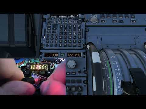
- 2x TM1637, 6-digit, 7-segment display, orange backlight
- EC11 Rotary encoder
- Arduino Nano
- Filter capacitors on the 5V rail:
- 100uF Electrolytic
- 10nF Polypropylene
Coming soon
Coming soon
- Power and MCU board
- Socket for the Arduino Nano board
- 5V Power line with reservoir and lowpass filter caps
- Connectors for the control and display board
- Control and display board
- 7seg1 - 6 digit display that is suited for frequencies (123.455)
- 7seg2 - another screen to be used in the context of each panel/mode. E.g. Active/Standby freqs, Nav1 and Nav2 freqs, VOR/ILS freqs, etc.
- Rotary 1 used by the Radionav part of the panel
- Rotary 1 Button (Switch) e.g. MHz/KHz
- Rotary 2 used by the FCU part of the panel
- Rotary 2 Button (FCU Push)
- Button 1 (Radionav Mode): switches the radio/navigation modes COM, NAV, ILS, XPDR, etc.
- Button 2 (Radionav Action) Send (Swap the frequencies)
- Button 3 (FCU Mode): switches independently between FCU values (ALT, HDG, SPD)
Libraries for Arduino:
FlightSimLibrary by Bits&Droids (RMP-mod)
- Download and install the Bits&Droids Flight Connector
- Import the Profile (or create youself the outputs: Active and Standby COM1 frequencies)
- Connect the Nano to a USB port and configure the device settings before hitting Start