Use a Raspberry Pi Zero and a few other components to build your compact close loop with OpenAPS
I am also working on an ultra compact Intel Edison version
I found an already working solution working with the Intel Edison, please use a 900MHz Explorer Board for Edison and refere to this guide.
Due to the closing of WirelessThings the RF module is not abailable anymore :(
(Everything in [ ] is only used for the initial setup)
- 1x Raspberry Pi Zero (Get a starter pack here)
- 1x Micro SD Card 8GB
To install Raspbian the OS the Raspberry Pi Zero is running - [Some way to connect your Raspberry Pi Zero to the internet]
- I used an Raspberry Pi 2 I had laying around (I basically set up Raspbian and downloaded everything following on the Raspberry Pi 2/3 and then swap the micro SD card to the Raspberry Pi Zero
- You also can use a WiFi USB dongle
- [1x Micro HDMI to HDMI adapter]
- [1x USB OTG to USB adapter]
- [Keyboard]
- 1x Micro SD Card 8GB
- 1x Power management aka PowerBoost (Power supply + Battery charger)
- 1x Battery
- 1x Radio Module All WirelessThings Products have been discontinued
*Why I am using the SRF module instead of the SliceOfRadio? Because it basically is just a breakout board of the SRF module and we can do it ourself:)* * 1x [**CC-Debugger**](http://www.aliexpress.com/item/CC-Debugger-CCxxxx-Bluetooth-ZIGBEE-Wireless-Emulator-Programmer-for-RF-System-on-Chips/32417465960.html?spm=2114.13010608.0.55.1gfz18) to flash the chip with a custom software * Some soldering skills + soldering equipment * A steady hand * Tools (tweezers, side cutters, double foam sided tape...) * Basic Linux knowledge (mainly on the commandline) * And of course an [OpenAPS compatible pump](http://openaps.readthedocs.io/en/master/docs/walkthrough/phase-0/hardware.html)
You will get a small portable Raspberry Pi Zero based device with a decent battery life (> 24 hours) and a much better and stabile communication to your pump. Thats all because we won't use that overpriced crappy CareLink stick.
You won't get a finished product that you can clip on like your insulin pump. It's basically just 3 PCBs glued together and bundled with a battery. I'm still working on a clip on option, but I still haven't had the right idea. Feel free to share yours:) You also won't get a complete guide on how to setup your close loop, but I include all the links, so just follow along and I am sure you will make it, if you can master diabetes you can you will master this!
Don't hesitate to ask me if you have any questions.
- You need to setup Raspbian, it is the operating system we use for the Raspberry Pi Zero
- Download here. We are using Jessie Light because we don't need the fully fledged Raspbian
- Once downloaded you need to burn the files to the SD card, follow this instructions and you are good to go
- Setup OpenAPS
- The best source is the webpage it self, it is worth reading through the documentation
- I don't use NightScout because I don't have any internet connectivity. Everything on my close loop happens locally.
- Prepare your radio module
- Follow this tutorial to flash the radio module, below you will find the color codes matching the colors used in the tutorial
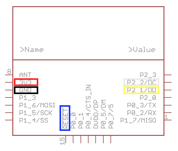
*This schematic is from [openmicros.org](http://openmicros.org/index.php/articles/88-ciseco-product-documentation/259-srf-technical-data)* 4. Setup [MMowlink](https://github.com/oskarpearson/mmeowlink/wiki/Installing-MMeowlink) (used to allow OpenAPS communicate with the radio module) if you have not already
Now swap your micro SD card in your Raspberry Pi Zero if you have not already
- If you want to access your Raspberry Pi Zero via USB there is an option for that 😊
**(This only works if you don't need the USB OTG port!)** * The Raspberry Pi Zero is capable of emulating USB devices with the USB OTG port, so we can simulate an Ethernet adapter. If you connect your Raspberry Pi Zero with your PC the Raspberry will create its own network. This allows you to directly SSH into your Raspberry Pi Zero. Please keep in mind, that if you enable this you won't be able to use a USB device on your Raspberry Pi Zero anymore. * If you want to extend the battery live of your close loop you can disable the HDMI components and the ACT LED * Disable HDMI **(Keep in mind that you won't get any output on the HDMI port if you do this)** * Edit `rc.local by executing `sudo nano /etc/rc.local` in your Raspberry Pis command line * Add `/usr/bin/tvservice -o` before `exit 0` * Disable ACT LED **(The ACT LED is the little green LED that indicates, that your Raspberry Pi Zero is running)** * Follow [this](http://www.jeffgeerling.com/blogs/jeff-geerling/controlling-pwr-act-leds-raspberry-pi) instructions
I recommend you to create a backup of your micro SD card, so you won't loos all the hard work!
Congratulations, the software part is done 👍
This may be a bit tricky if this is your first solder job, take your time and don't be frustrated if it is not working the first time.
I am using an enamelled copper wire, so everything looks cleaner, but you can use normal wires to.
Make sure, that there is some sort of isolation around the wires, so you won't short out your Raspberry Pi Zero
- We want to power the Raspberry Pi Zero
-
We can glue the PowerBoost PCB on the back of the Raspberry Pi Zero like this
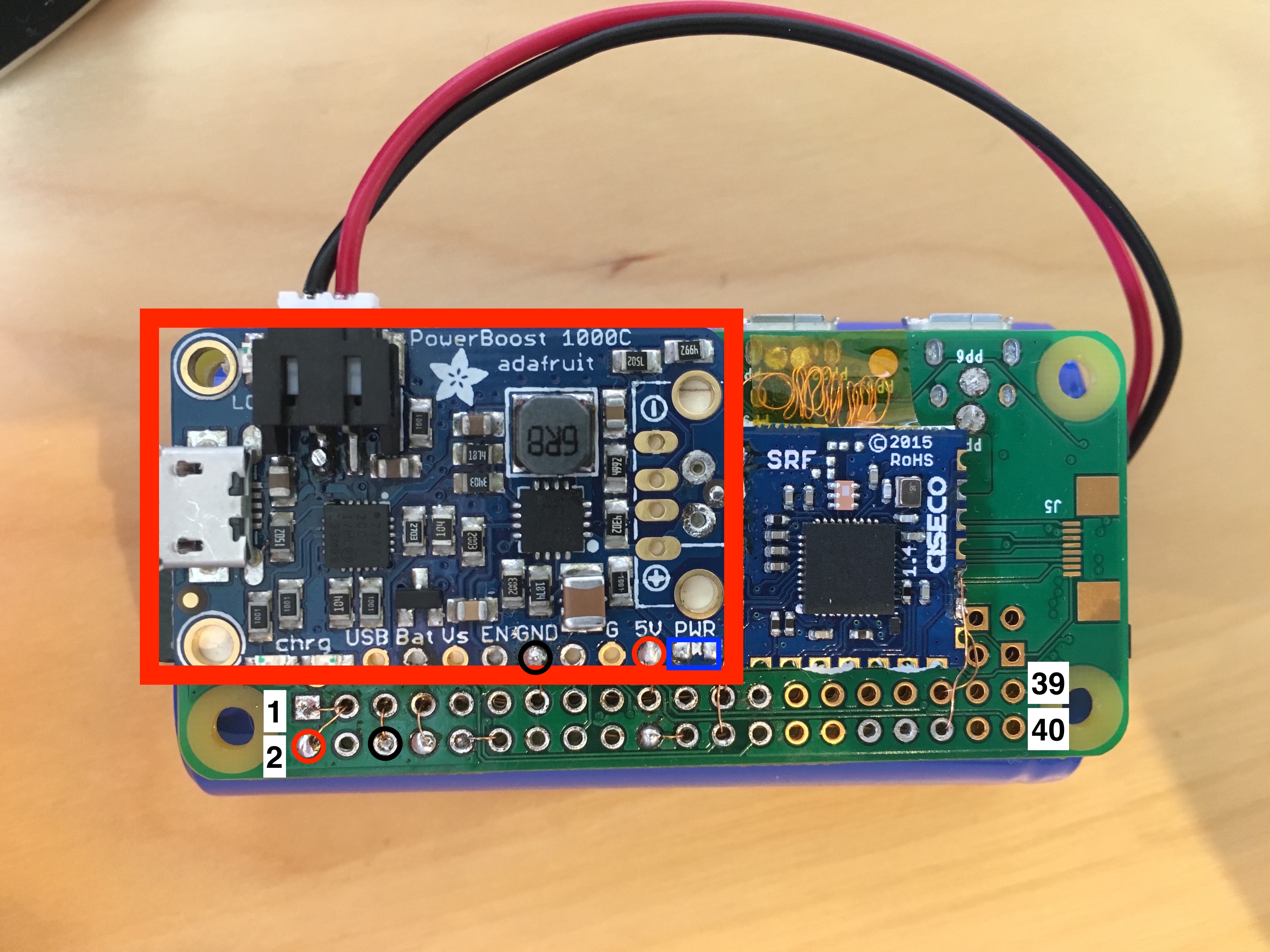 As a pro tip I also desoldered the PWR LED of the PowerBoost PCB (lower right side on the board), so can sleep better and won't get blind when looking at it.
I am using a very strong double sided foam tape, be careful when placing it on the Raspberry Pi Zero, it is very hard to remove!
-
Next we need to solder the power wires from the PowerBoost to the Raspberry Pi Zero
- 5V: Solder a wire from the PowerBoosts 5V output (on the lower side of the board) to the Raspberry Pi Zeros 5V GPIO pin 2
- GND: Solder a wire from the PowerBoosts GND output (also on the lower side of the board) to the Raspberry Pi Zeros GND GPIO pin 6
**Be careful when soldering directly to the GPIO pins. We are using the Raspberry Pi upside down, so double check what hole you solder to, desoldering is a pain in the arse if you don't have the right tools!**
When you think everything is soldered correctly you can connect the battery. Your Raspberry Pi Zero should run from the battery if everything went well:) * If you disabled the ACK LED you will only see a very quick flash * You also can connect your Raspberry Pi Zero to the battery and also plug in the USB cable into Raspberry Pi Zeros USB OTG port to SSH into it. * **Disconnect the power again!**
- Communicate with the insulin pump
- Her we first solder every wire to the SRF board, then glue it down and then solder the wires to the Raspberry Pi Zero
- Solder the wires according to the color in the picture below.
**Again, make sure to solder to the right holes!** 
- Choose the right frequency
- By default the MMowlink will use the US frequency which is awesome if you live in the US and have an US pump, but for us non US citizens we need to do an additional step
- Every time the Raspberry Pi Zero boots we need to execute a little command to tune it for the World Wide frequency band
- Edit
rc.localby executingsudo nano /etc/rc.localin your Raspberry Pis command line - Add
su pi -c '/home/pi/mmeowlink-source/bin/mmtune.py --port /dev/ttyAMA0 --radio_local WW --serial <PUMP_SERIAL_NUMBER> < /dev/null &'beforeexit 0
*WW means World Wide* - Edit
- Every time the Raspberry Pi Zero boots we need to execute a little command to tune it for the World Wide frequency band
- [Optional] Increase the range with an antenna
- With the SRF module we already have a greater range then with the CareLink USB stick, but we can tweak it a bit by soldering an approximately 8cm (3,14 inch) wire to the SRF modules antenna hole. With this you can even penetrate a wall!
- Now check if everything works
- The best way to check if everything works is to communicate with the pump
Do this by `cd` in your `openaps` directory on your Raspberry Pi Zero, then you can execute `openaps use status` to get the current status of your pump. If you get a response that is formatted like a JSON everything you have done was right!
If something is not working you need to find the issue. There is a trouble shooting guide below.
Congratulations, your ZeroAPS is ready to use now 🎉
Please be careful and don't destroy your Raspberry Pi Zero!
This is more of a bloody hack, but it will make it more compact. My goal is to have only one USB port on the Raspberry Pi, but the PowerBoost won't let us access the data pins of the micro USB, so we will use 2 micro USB ports for now. (I already contacted Adafruit because of that feature)
You can desolder the HDMI port and both micro USB ports of the Raspberry Pi. This makes it really flat. To compensate the lost USB OTG and power port you can glue an micro USB breakout board to a spare place on the other side of the Raspberry Pi Zero
- Desolder the USB ports
**(First make sure you don't need them in the future, e.g for Dexcom receiver)** * Get power * Solder **GND** to **GND** of the PowerBoost * Solder **VCC (or 5V)** to **Bat** of the PowerBoost * Get data *(Directly solder to the gold pads on the Raspberry Pi)* * Solder **D+** to **PP22** * Solder **D-** to **PP23**
- Desolder the HDMI port
- Yep, thats all 😊
I will update this when I make any changes
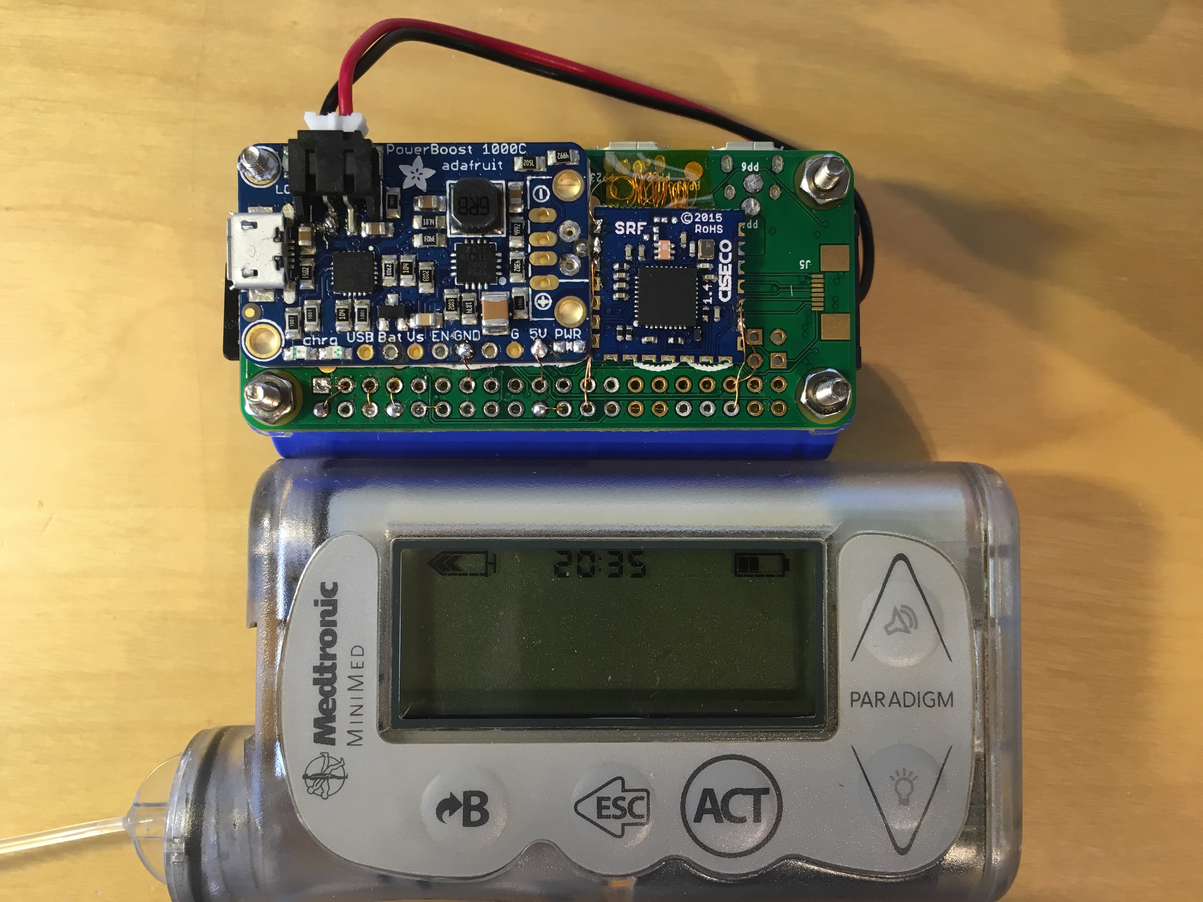 ZeroAPS from the top compared to a Paradigm 754
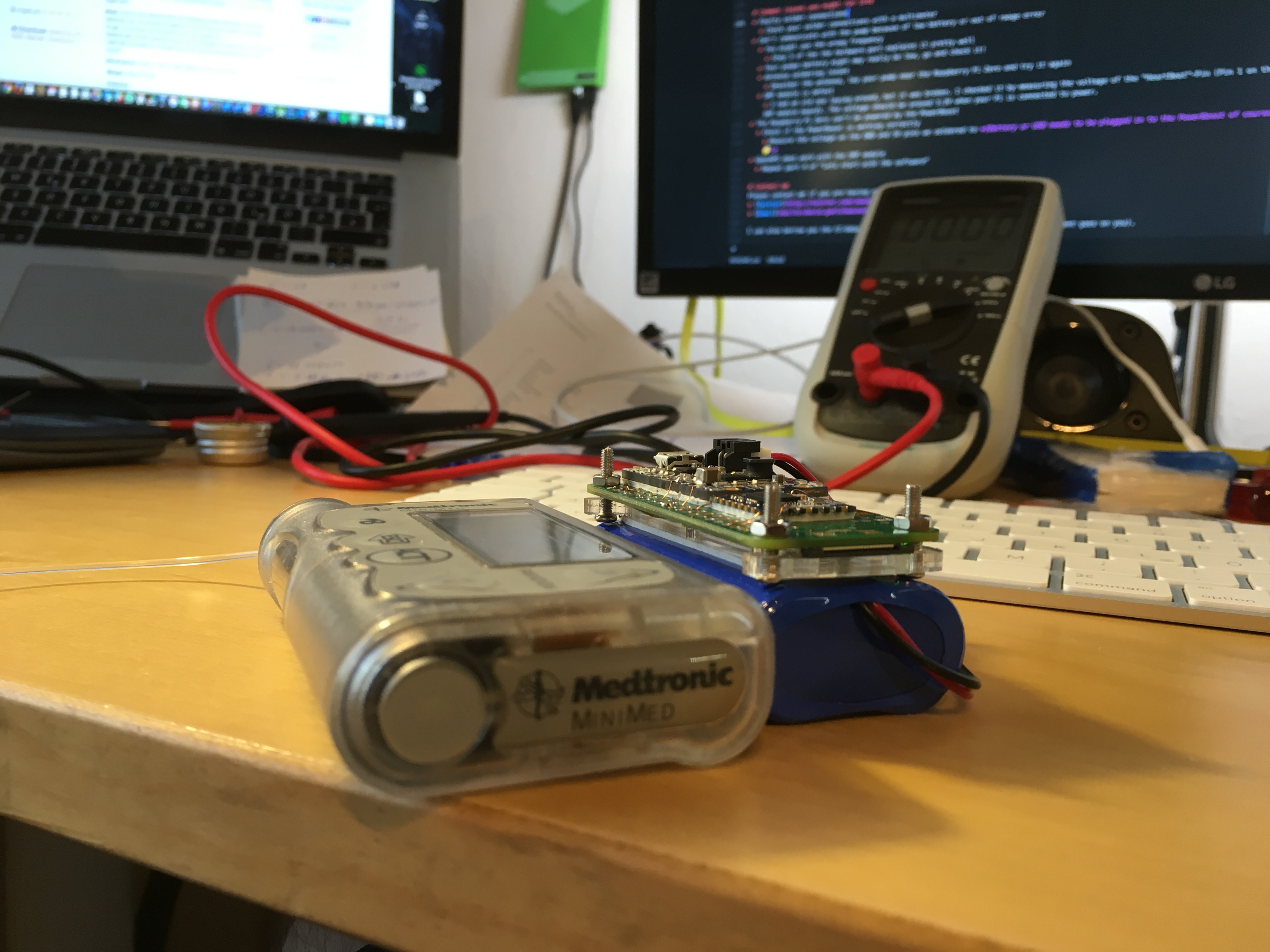 ZeroAPS from the side compared to a Paradigm 754
The current power consumption is about 140mA (If you disabled the ACT LED and the HDMI)
With a 4400mAh battery we should have a battery live of about 31 hours which is not bad 😊
- Faulty solder connections
- Check your solder connections with a multimeter
- Can't communicate with the pump because of "low battery" or "Out of range" error
- You might use the wrong frequency
- Step 3 of the the hardware part explains it well
- Your pumps battery may really be low, go and check it!
- Antenna soldering issues
- Desolder the antenna, lay your pump near the Raspberry Pi Zero and try it again
- SRF module is defect
- I had an old one laying around, but it was broken. I checked it by measuring the voltage of the "HeartBeat"-Pin (Pin 1 on the SRF module board). The voltage should be around 3.3V when your Pi is connected to power.
- You might use the wrong frequency
- The Raspberry Pi Zero can't be powered by the PowerBoost, but everything works when connecting the Pi directly to a USB port
- Check if the PowerBoost is working correctly
- Measure the voltage on the GND and 5V pins we soldered to (Battery or USB needs to be plugged in to the PowerBoost of course 😊)
- Measure the voltage of the battery by connecting the multimeter leads to the Bat and GND hole. The voltage should be between 4.1V (Max) to 3.2V (Min, the red LOW LED will light up)
- Check if the PWR LED is on. If you desoldered it, like I did, you can check the voltage. There should be around 5V.
- Check if the PowerBoost is working correctly
- OpenAPS does work with the SRF module
- Repeat part 4 of "Lets start with the software"
Please contact me if you are having questions about ZeroAPS.
I can also borrow you the CC-Debugger if you live in Germany or Austria (Shipment goes on you).