


An electronic lock which can be unlocked when the correct passcode is entered though a DTMF Keypad accompanied by a 16x2 LCD Display which displays the same. When the passcode is entered in the DTMF Keypad, that data is decoded and the necessary details are sent to a 16x2 LCD Display to display the same and is also compared with the already set passcode [which can be altered if necessary, only by entering the current passcode (as a security measure)] and if they are same sends the necessary signals to unlock the electronic fail-secure lock.
 |
|---|
| 16x2 LCD Display with a DTMF Keypad |
The main objective of our design project is to design and implement a locking mechanism, which can be unlocked using a passcode via DTMF decoder and all the information being displayed on the 16x2 LCD display, the design was limited to a solenoid actuator as the locking mechanism since this is just a prototype and it was implemented using ATmega328P microcontroller as the project's brain.
Though practically on any passcode lock I use a keypad on for input code, here I am trying on interfacing it with DTMF input through a DTMF decoder since it provides an advantage of being able to literally make a call from any point in the world to unlock this.
And also as future plans I also wish to interface a keyboard on to the setup like in any normal passcode locks. One of the main application is a passcode door lock.
The objective is to create a passcode unlockable lock with a display which shows each and every required instructions and the cost of the model is low compared to existing models in the market and also the model consumes less power (other than the locking mechanism) and so it has very relaiable battery backup (due to low power consumption).
 |
|---|
| Image of wired working circuit |
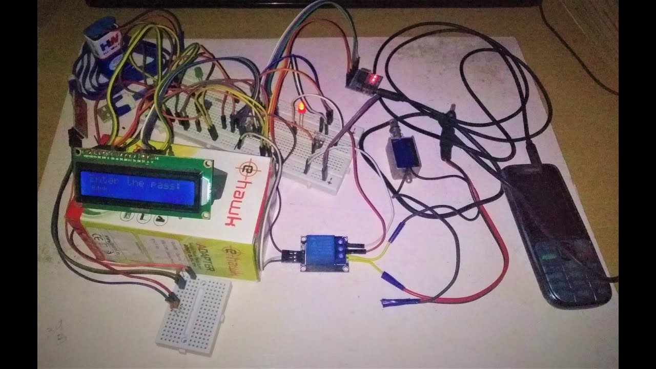
If you want to recreate this project install Arduino IDE and buy all the components mentioned in "Componenents Required" section and connect everything as per below circuit diagrams below and insert the code in the repo to the microcontroller using Arduino IDE and the programming circuit.
 |
|---|
| Schematic of the Main Circuit |
 |
|---|
| Breadboard Wiring of the Main Circuit |
 |
|---|
| Schematic of the Programming Circuit |
 |
|---|
| Breadboard Wiring of the Programming Circuit |
I chose ATmega328P since I required a microcontroller but I didn't know Assembly Language Programming required to use a microcontroller. I burned Arduino Uno bootloader to the microcontroller so that I could code it using Arduino code which I knew. To use ATmega328P microcontroller as Arduino on breadboard I required just a 16 MHz crystal along with two 22pF ceramic capacitor. But to program I required an extra 100nF ceramic capacitor. All the connections are avalable in schematics above. The reference used for this is in "Reference" section.
I used MT8870 DTMF Decoder Module since it provides information on the key pressed on DTMF keypad a 4-bit code for a key so in total 16 keys. The interfacing, working and further information along with reference to datasheet is available in "Component Study" section.
The 16x2 LCD is very easy to interface with Arduino board, which is the exact reason why I chose it as the display for our project. The interfacing, working and further information along with reference to datasheet is available in "Component Study" section.
The 12V Soleniod was the best component available to us to demonstrate the locking function that I required. Since this is a prototype, as I develop further I will be making significant changes. The interfacing, working and further information along with reference to datasheet is available in "Component Study" section.
For interfacing LEDs I know that both our supply and microcontroller output voltage are 5V and that the forward current of the LED to be 10mA from LED datasheet. So using the equation:
Substituting,
So, approximately I took 330
Since using relay without proper circuits required might cause back emf voltage spike or some other undesired event, which is the reason why I chose the Relay Module. The circuit consists of a transistor an LED and few resistors. Here the transistor provides protection. A transistor in between will allow a 5V signal from the microconytroller to switch a 12V signal via the transistor to the relay - thus turning it On. The LED is connected in such a way that it will be lit when the relay is turned On. In the event of a back emf voltage spike or some other undesired event only your transistor will be blown, instead of the entire circuit. The interfacing, working and further information along with reference to datasheet is available in "Component Study" section.
The FT232RL USB to UART TTL Module is the best module available in the market which supports serial programming that is supported by the microcontroller. The interfacing, working and further information along with reference to datasheet is available in "Component Study" section.
Once the whole circuit was wired I tested it multiple times to ensure the reliability of the prototype. The details of a few tests are given below.
| Test # | Description | Outcome |
|---|---|---|
| 1 | Unlocking | |
| 2 | Locking | |
| 3 | Changing Passcode | |
| 4 | Changing Passcode | |
| 5 | Wrong Passcode | |
| 6 | Wrong Passcode | |
| 7 | Unlocking | |
| 8 | Unlocking | |
| 9 | Locking | |
| 10 | Wrong Passcode |
Since out of 10 tests, the prototype only failed about twice, therefore I can conclude that the design is about 80% - 90% reliable. Since I are developing the prototype, I are sure that I I'll be able to make tremendous progress.
I simulated the prototype by replacing the microcontroller with Arduino Uno board since, I're using Arduino on breadboard which is not available for simulation in Proteus 8 Professional. Also for simulation the DTMF Decoder Module was also not available in Proteus 8 Professional so I used an alternative setup from a site Foros de Electronica a spanish Electronics Forum which is available in the reference. The prototype simulation worked out fine, which helped us ensure that our code is correct and working.
 |
|---|
| Screenshot of Simulation in Proteus 8 Professional |
The working can be expained mainly by explaining in detail the interfacing of the main components in the project with the microcontroller. And rest of the part can be explained using the code that was given to the microcontroller, i.e.,
- Interfacing of DTMF Decoder Module
- Interfacing of 16x2 LCD Display
- Interfacing of Relay Module
- Code
The DTMF Decoder Module connections are there in the above schematics and it's working is explained in "Component Study" section. As I know the output of the module is a binary code which indicates any one value on the DTMF keypad as well a bit that indicates whenever DTMF tone is recieved so I just gave this as input to 5 digitals pins of the microcontroller and wrote the code to recognize what the user's input is.
The 16x2 LCD Display connections are there in the above schematics. Now here I just used the respective codes which are explained in "Component Study" section to display all the information on the LCD Display. The information I display are :-
- Press any key
- Enter the pass: ****
- Correct Passcode Or
-
- Wrong Passcode! - returns to instruction 1
- Press # - UNLOCK
-
- * - CHANGE PASS
- UNLOCKED! Or
-
- Enter new pass: 1234
- Press # to LOCK Or
-
- New passcode set 1234 - returns to instruction 1
- LOCKED! - returns to instruction 1
The Relay Module connections are there in the above schematics and it's working is explained in "Component Study" section.. As I know that I use relay as a switch to On/Off high voltage components by applying low voltage so, I take an output from a digital pin of the microcontroller as our input to relay to turn On/Off the Solenoid Actuator (works at 12V - 1A).
Since I have a normally closed terminal which disconnects when relay is actuated, I connect a red LED here to indicate the Off/Locked state of the Solenoid.
And when the Solenoid ("Component Study" section.) is actuated I have coded the microcontroller to give an output on a digital pin which is connected to a green LED to indicate the On/Unlocked state of the Solenoid.
I are using ATmega328P microcontroller and I've burned Arduino Uno bootloader to it. Also there is a programming circuit saperately for programming the microcontroller which can be easily understood by just referring the connections in the above schematics. So, I use Arduino coding itself to program the microcontroller. The code is pretty self explanatory with proper comments. The code is uploaded in the repository. The code snippet is available below as well.
#include <LiquidCrystal.h> // Library for 16x2 LCD Display
const int rs = 8, en = 7, d4 = 6, d5 = 5, d6 = 4, d7 = 3; // initialize the library by associating any needed LCD interface pin with the IC pin number it is connected to
LiquidCrystal lcd(rs, en, d4, d5, d6, d7);
// Function declarations
int DTMF(); // Function to read a number key pressed using a DTMF Decoder
int PressAnyKey(); // Function to know if any key is pressed
char CorrectPasscode(); // Function to read next input (* or #) if user passcode matched to preset one
char Lock(); // Function to read # if user pressed it to lock the device
// Global variable declarations
int DTMFdata; // Initialize the DTMF data variable for decimal of 4 bit binary.
int DTMFvalue; // Variable to indicate the value of the actual key pressed for DTMF()
char DTMFvalue1; // Variable to indicate the value of the actual key pressed for CorrectPasscode()
char DTMFvalue2; // Variable to indicate the value of the actual key pressed for Lock()
int StQ = 9; // DTMF Module StQ Pin connects to IC Digital Pin 9
int Q4 = 10; // DTMF Module Q4 Pin connects to IC Digital Pin 10
int Q3 = 11; // DTMF Module Q3 Pin connects to IC Digital Pin 11
int Q2 = 12; // DTMF Module Q2 Pin connects to IC Digital Pin 12
int Q1 = 13; // DTMF Module Q1 Pin connects to IC Digital Pin 13
int Passcode[4] = {0, 0, 0, 0}; // Array for storing the passcode
// void setup() starts
void setup()
{
lcd.begin(16, 2);
pinMode(Q1, INPUT); // Declaring the pinModes of other pins of the IC that is used
pinMode(Q2, INPUT); // Declaring the pinModes of other pins of the IC that is used
pinMode(Q3, INPUT); // Declaring the pinModes of other pins of the IC that is used
pinMode(Q4, INPUT); // Declaring the pinModes of other pins of the IC that is used
pinMode(StQ, INPUT); // Declaring the pinModes of other pins of the IC that is used
pinMode(2, OUTPUT); // Declaring the pinModes of other pins of the IC that is used
pinMode(1, OUTPUT); // Declaring the pinModes of other pins of the IC that is used
}
// void setup() ends
// void loop() starts
void loop()
{
// Variable declarations
int Entered_Passcode[4]; // Array to store the passcode input by user
int Any_Key = 0; // Variable used to acknowledge if any key was pressed
int Compare = 0; // Variable for comparison of user entered passcode
int i,j,k,l; // Variables for 'for loop'
char NextInput; // Variable to collect next input
int Lock1 = 2; // Variable storing digital pin number to which lock is connected
int LED = 1; // Variable storing digital pin number to which LED Green is connected
char LockInput; // Variable to collect # to lock device
// Variable declarations ends
// Idle Mode starts
// Code to print the Idle mode display "Press any key_"
lcd.home();
lcd.print("Press any key");
// Code to print the Idle mode display "Press any key_" ends
// Device leaving Idle mode....
// If statement for unlocking or resetting the passcode starts
Any_Key = PressAnyKey();
delay(100);
if(Any_Key == 1)
{
// LCD code to print "Enter the passcode:" on display
lcd.clear();
lcd.home();
lcd.print("Enter the pass:");
lcd.setCursor(0,1);
lcd.cursor();
// LCD code to print "Enter the passcode:" on display ends
// for loop to obtain passcode from user to Entered_Passcode variable
for(i=0 ; i<4 ; i++)
{
Entered_Passcode[i] = DTMF();
// Code to print "*" on display when a number is pressed
lcd.setCursor(i,1);
lcd.print('*');
delay(100);
// Code to print "*" on display when a number is pressed ends
}
// for loop to obtain passcode from user to Entered_Passcode variable ends
// for loop to compare passcode from user to preset passcode
for(j=0 ; j<4 ; j++)
{
if(Passcode[j] == Entered_Passcode[j])
{
Compare++;
}
}
// for loop to compare passcode from user to preset passcode ends
// if statement to do further proceedings if the entered passcode is correct
if(Compare == 4)
{
// Code to print instructions on LCD and wait for next input
lcd.clear();
lcd.home();
lcd.noCursor();
lcd.print("Correct Passcode");
delay(1000);
lcd.clear();
lcd.home();
lcd.print("Press # - UNLOCK");
lcd.setCursor(1,1);
lcd.print("* - CHANGE PASS");
NextInput = CorrectPasscode();
delay(500);
// Code to print instructions on LCD and wait for next input ends
switch(NextInput)
{
case '*':
// LCD code to enter new passcode
lcd.clear();
lcd.home();
lcd.print("Enter new pass:");
lcd.setCursor(0,1);
lcd.cursor();
for(k=0 ; k<4 ; k++)
{
Passcode[k] = DTMF();
// Code to print "*" on display when a number is pressed
lcd.setCursor(k,1);
lcd.print('*');
delay(100);
// Code to print "*" on display when a number is pressed ends
}
lcd.clear();
lcd.home();
lcd.noCursor();
lcd.print("New passcode set");
for(l=0 ; l<4 ; l++)
{
lcd.setCursor(l,1);
lcd.print(Passcode[l]);
}
delay(1000);
// LCD code to enter new passcode ends
lcd.clear();
goto End;
break;
case '#':
// LCD code to unlock device
digitalWrite(Lock1, HIGH);
digitalWrite(LED, HIGH);
lcd.clear();
lcd.home();
lcd.print("UNLOCKED!");
delay(1000);
// LCD code to unlock device ends
// LCD code to lock device
lcd.clear();
lcd.home();
lcd.print("Press # to LOCK");
LockInput = Lock();
delay(500);
if(LockInput == '#')
{
lcd.clear();
lcd.home();
lcd.print("LOCKED!");
digitalWrite(Lock1, LOW);
digitalWrite(LED, LOW);
delay(1000);
// LCD code to lock device ends
lcd.clear();
goto End;
}
break;
}
}
// if statement to do further proceedings if the entered passcode is correct ends
// else statement to do further proceedings if the entered passcode is incorrect
else
{
lcd.clear();
lcd.home();
lcd.noCursor();
lcd.print("Wrong Passcode!");
delay(1000);
lcd.clear();
goto End;
}
// else statement to do further proceedings if the entered passcode is incorrect ends
}
// If statement for unlocking or resetting the passcode ends
End:
delay(0);
}
// void loop() ends
// DTMF Function Starts
int DTMF()
{
// IF StQ is High a DTMF tone is present. Check 4-bit code.
// While loop starts
while(1)
{
DTMFdata = 0;
DTMFvalue = '\0';
// If statement starts
if (digitalRead(StQ) == HIGH)
{
if (digitalRead(Q1) == HIGH) // If Q1 High add 1 to DTMFdata
{
DTMFdata = DTMFdata + 1;
}
if (digitalRead(Q2) == HIGH) // If Q2 High add 2 to DTMFdata
{
DTMFdata = DTMFdata + 2;
}
if (digitalRead(Q3) == HIGH) // If Q3 High add 4 to DTMFdata
{
DTMFdata = DTMFdata + 4;
}
if (digitalRead(Q4) == HIGH) // If Q4 High add 8 to DTMFdata
{
DTMFdata = DTMFdata + 8;
}
// decode 4-bit code. Which button was pressed?
// Switch statement starts
switch (DTMFdata)
{
case 0: //D
continue;
break;
case 1: //1
DTMFvalue = 1; // Setting the value of the actual key pressed to DTMFvalue variable
break;
case 2: //2
DTMFvalue = 2; // Setting the value of the actual key pressed to DTMFvalue variable
break;
case 3: //3
DTMFvalue = 3; // Setting the value of the actual key pressed to DTMFvalue variable
break;
case 4: //4
DTMFvalue = 4; // Setting the value of the actual key pressed to DTMFvalue variable
break;
case 5: //5
DTMFvalue = 5; // Setting the value of the actual key pressed to DTMFvalue variable
break;
case 6: //6
DTMFvalue = 6; // Setting the value of the actual key pressed to DTMFvalue variable
break;
case 7: //7
DTMFvalue = 7; // Setting the value of the actual key pressed to DTMFvalue variable
break;
case 8: //8
DTMFvalue = 8; // Setting the value of the actual key pressed to DTMFvalue variable
break;
case 9: //9
DTMFvalue = 9; // Setting the value of the actual key pressed to DTMFvalue variable
break;
case 10: //0
DTMFvalue = 0; // Setting the value of the actual key pressed to DTMFvalue variable
break;
case 11: //*
continue;
break;
case 12: //#
continue;
break;
case 13: //A
continue;
break;
case 14: //B
continue;
break;
case 15: //C
continue;
break;
}
// Switch statement ends
break; // To break the infinite while loop
}
// If statement ends
}
// While loop ends
return DTMFvalue; // Return the value stored in variable DTMFvalue
}
// DTMF Function ends
// PressAnyKey Function starts
int PressAnyKey()
{
// While loop starts
while(1)
{
// If statement starts
if (digitalRead(StQ) == HIGH)
{
break; // To break the infinite while loop
}
// If statement ends
}
// While loop ends
return (1); // Returns 1
}
// PressAnyKey Function ends
// CorrectPasscode Function Starts
char CorrectPasscode()
{
// IF StQ is High a DTMF tone is present. Check 4-bit code.
// While loop starts
while(1)
{
DTMFdata = 0;
DTMFvalue1 = '\0';
// If statement starts
if (digitalRead(StQ) == HIGH)
{
if (digitalRead(Q1) == HIGH) // If Q1 High add 1 to DTMFdata
{
DTMFdata = DTMFdata + 1;
}
if (digitalRead(Q2) == HIGH) // If Q2 High add 2 to DTMFdata
{
DTMFdata = DTMFdata + 2;
}
if (digitalRead(Q3) == HIGH) // If Q3 High add 4 to DTMFdata
{
DTMFdata = DTMFdata + 4;
}
if (digitalRead(Q4) == HIGH) // If Q4 High add 8 to DTMFdata
{
DTMFdata = DTMFdata + 8;
}
//decode 4-bit code. Which button was pressed?
// Switch statement starts
switch (DTMFdata)
{
case 0: //D
continue;
break;
case 1: //1
continue;
break;
case 2: //2
continue;
break;
case 3: //3
continue;
break;
case 4: //4
continue;
break;
case 5: //5
continue;
break;
case 6: //6
continue;
break;
case 7: //7
continue;
break;
case 8: //8
continue;
break;
case 9: //9
continue;
break;
case 10: //0
continue;
break;
case 11: //*
DTMFvalue1 = '*'; // Setting the value of the actual key pressed to DTMFvalue variable
break;
case 12: //#
DTMFvalue1 = '#'; // Setting the value of the actual key pressed to DTMFvalue variable
break;
case 13: //A
continue;
break;
case 14: //B
continue;
break;
case 15: //C
continue;
break;
}
// Switch statement ends
break; // To break the infinite while loop
}
// If statement ends
}
// While loop ends
return DTMFvalue1; // Return the value stored in variable DTMFvalue
}
// CorrectPasscode Function ends
// Lock Function Starts
char Lock()
{
// IF StQ is High a DTMF tone is present. Check 4-bit code.
// While loop starts
while(1)
{
DTMFdata = 0;
DTMFvalue2 = '\0';
// If statement starts
if (digitalRead(StQ) == HIGH)
{
if (digitalRead(Q1) == HIGH) // If Q1 High add 1 to DTMFdata
{
DTMFdata = DTMFdata + 1;
}
if (digitalRead(Q2) == HIGH) // If Q2 High add 2 to DTMFdata
{
DTMFdata = DTMFdata + 2;
}
if (digitalRead(Q3) == HIGH) // If Q3 High add 4 to DTMFdata
{
DTMFdata = DTMFdata + 4;
}
if (digitalRead(Q4) == HIGH) // If Q4 High add 8 to DTMFdata
{
DTMFdata = DTMFdata + 8;
}
//decode 4-bit code. Which button was pressed?
// Switch statement starts
switch (DTMFdata)
{
case 0: //D
continue;
break;
case 1: //1
continue;
break;
case 2: //2
continue;
break;
case 3: //3
continue;
break;
case 4: //4
continue;
break;
case 5: //5
continue;
break;
case 6: //6
continue;
break;
case 7: //7
continue;
break;
case 8: //8
continue;
break;
case 9: //9
continue;
break;
case 10: //0
continue;
break;
case 11: //*
continue;
break;
case 12: //#
DTMFvalue2 = '#'; // Setting the value of the actual key pressed to DTMFvalue variable
break;
case 13: //A
continue;
break;
case 14: //B
continue;
break;
case 15: //C
continue;
break;
}
// Switch statement ends
break; // To break the infinite while loop
}
// If statement ends
}
// While loop ends
return DTMFvalue2; // Return the value stored in variable DTMFvalue
}
// Lock Function ends

The DTMF tone required (i.e., the key that was pressed) is obtained from a mobile phone via an AUX cable to the DTMF decoder module which is connected to the microcontroller. The DTMF decoder module sends this information to the microcontroller where the data is processed and respective commands to display the instructions on the 16x2 LCD display are run. Further, as the user follows the instructions on the LCD display, when the user press the respective key to unlock the microcontroller processes this information and respective commands to activate the relay are run. Since, the solenoid circuit's swictch here is the relay, when the relay is activated, the solenoid is also actuated.
 |
|---|
| Veecome Electronic Digital Number Keypad Password Lock for Cabinet Door Drawer Code Lock Price: $18.19 |
 |
|---|
| Zyyini Door Lock, Zinc Alloy Electronic Password Lock Anti-Theft Home Security Door Lock with 2 Mechanical Key Price: $39.99 |
 |
|---|
| Milestone Systems Electronic Door Lock Price: $184.93 |
The drawbacks of the existing models are:
- Expensive.
- Lacks display (there are models with display but they are more expensive compared to the models without display I have shown here).
- Consumes too much power (compared to the model I'm designing).
The advantages of our model over the existing ones are:
- Cheap compared to the existing models.
- Has a display.
- Low power consumption compared to the existing models.
| Sl No. | Component Name | Quantity |
|---|---|---|
| 1. | MT8870 DTMF Decoder Module | 1 |
| 2. | 16x2 LCD Display | 1 |
| 3. | Microcontroller (ATMEGA328P with Uno Bootloader) | 1 |
| 4. | 12V Solenoid Actuator | 1 |
| 5. | 5V Relay Module | 1 |
| 6. | FT232RL USB to UART TTL Module | 1 |
| 7. | Ceramic Capacitor 100nF | 2 |
| 8. | Ceramic Capacitor 22pf | 4 |
| 9. | Crystal Oscillator 16Mhz | 2 |
| 10. | LED 5mm Green | 1 |
| 11. | LED 5mm Red | 1 |
| 12. | T connector for 9V battery | 1 |
| 13. | IC LM7805 | 1 |
| 14. | Jumper Wires | - |
| 15. | Breadboard | 1 |
| 16. | Trimpot 10kΩ | 1 |
| 17. | Adapter 12V DC | 1 |
| 18. | Aux Cable | 1 |
| 19. | Mini USB Cable | 1 |
| 20. | IC Base for ATmega328P | 1 |
| 21. | Resistors 330Ω | 2 |
| 22. | Headstrips for LCD Display | - |
| 23. | 9V Battery | 1 |
| 24. | Rocker Switch | 1 |
| 25. | Push Button | 1 |
| 26. | Breadboard Wire | - |
The software used during the course of completion of our project:
Fritzing is an open-source initiative to develop amateur or hobby CAD software for the design of electronics hardware, to support designers and artists ready to move from experimenting with a prototype to building a more permanent circuit. I used this for drawing schematic of the circuit and to generate breadboard wiring diagram.
The open-source Arduino Software (IDE) makes it easy to write code and upload it to the board. This software can be used with any Arduino board. Since I have burned Arduino Uno bootloader to ATmega328P, therefore I use this software itself to write the code.
The Proteus Design Suite is a proprietary software tool suite used primarily for electronic design automation. The software is used mainly by electronic design engineers and technicians to create schematics and electronic prints for manufacturing printed circuit boards. I used this for simulation of the circuit.
 |
|---|
| MT8870 DTMF Decoder Module |
The MT8870 based DTMF (Dual Tone Multi-Frequency) decoder module is commonly used to control robots with a mobile phone, it is also used in different kinds of home automation projects where mobile dial pad input is required. This module works as a tone decoder that uses its 3.5 mm audio connector socket to get the input audio signal. It is popularly used for mobile and fixed telephone voice dialing and recording related functions.
DTMF is commonly found in tone based dial pad devices such as mobile phones or telephones dial pad. When the dial pad is pressed, it produces a combination of two separate sine waves which is a unique frequency signal that can be decoded and produced as a binary output. MT8870 based DTMF module does exactly the same thing. The pressed button can easily be identified by checking the binary output. It can produce binary output by getting tone input from 0-9 number, A - D letters, * and # symbols. The important components on the MT8870 DTMF Module are marked below.
 |
|---|
| Important Components of DTMF Decoder Module |
The binary output digits are available on the output pin Q1 to the pin Q4. In this module, there are onboard LEDs that can be very useful to identify the output state signal of the binary pins.
The DTMF module has a 3.5 mm audio input Jack that can be easily connected with a mobile phone by using a 3.5mm audio jack. It is very useful to add dual-tone multi-frequency decoding in any microcontroller based projects. The datasheet can be found in "Reference" section.
| Pin Name | Function | Comment |
|---|---|---|
| Q1 | Binary Bit 1 | LSB |
| Q2 | Binary Bit 2 | - |
| Q3 | Binary Bit 3 | - |
| Q4 | Binary Bit 3 | MSB |
| StQ | Delayed String Output | Represents Binary Bit 0 - Gives output when a button is pressed |
| Power Down Input | To be grounded | |
| IN | Inhibit Input | Logic high inhibits the detection of tones representing characters A, B, C and D |
| VCC | DC Supply Input | 4.5V - 5.5V (5.0V Nominal) |
| GND | Ground | - |
| Key | IN | StQ | Q4 | Q3 | Q2 | Q1 |
|---|---|---|---|---|---|---|
| 1 | - | H | 0 | 0 | 0 | 1 |
| 2 | - | H | 0 | 0 | 1 | 0 |
| 3 | - | H | 0 | 0 | 1 | 1 |
| 4 | - | H | 0 | 1 | 0 | 0 |
| 5 | - | H | 0 | 1 | 0 | 1 |
| 6 | - | H | 0 | 1 | 1 | 0 |
| 7 | - | H | 0 | 1 | 1 | 1 |
| 8 | - | H | 1 | 0 | 0 | 0 |
| 9 | - | H | 1 | 0 | 0 | 1 |
| 0 | - | H | 1 | 0 | 1 | 0 |
| * | - | H | 1 | 0 | 1 | 1 |
| # | - | H | 1 | 1 | 0 | 0 |
| A | L | H | 1 | 1 | 0 | 1 |
| B | L | H | 1 | 1 | 1 | 0 |
| C | L | H | 1 | 1 | 1 | 1 |
| D | L | H | 0 | 0 | 0 | 0 |
| A | H | L | - | - | - | - |
| B | H | L | - | - | - | - |
| C | H | L | - | - | - | - |
| D | H | L | - | - | - | - |
 |
|---|
| 16x2 LCD Display |
LCD modules are very commonly used in most embedded projects, the reason being its cheap price, availability and programmer friendly. Most of us would have come across these displays in our day to day life, either at PCO’s or calculators. The appearance and the pinouts have already been visualized above now let us get a bit technical.
16×2 LCD is named so because; it has 16 Columns and 2 Rows. There are a lot of combinations available like, 8×1, 8×2, 10×2, 16×1, etc. but the most used one is the 16×2 LCD. So, it will have (16×2=32) 32 characters in total and each character will be made of 5×8 Pixel Dots. A Single character with all its Pixels is shown in the below picture.
 |
|---|
| Pixels of a single character |
Now, I know that each character has (5×8=40) 40 Pixels and for 32 Characters I will have (32×40) 1280 Pixels. Further, the LCD should also be instructed about the Position of the Pixels. Hence it will be a hectic task to handle everything with the help of MCU, hence an Interface IC like HD44780is used, which is mounted on the backside of the LCD Module itself. The function of this IC is to get the Commands and Data from the MCU and process them to display meaningful information onto our LCD Screen. You can learn how to interface an LCD using the above mentioned links. If you are an advanced programmer and would like to create your own library for interfacing your Microcontroller with this LCD module then you have to understand the HD44780 IC is working and commands which can be found its datasheet.
| Pin # | Pin Name | Description |
|---|---|---|
| 1 | VSS | GND |
| 2 | VDD | VCC (+5V DC) |
| 3 | VE | Decides the contrast level of display. |
| 4 | RS (Register Select) | Connected to Microcontroller to shift between command/data register |
| 5 | RW (Read/Write) | Normally grounded to write data to LCD |
| 6 | E (Enable) | Connected to Microcontroller Pin and toggled between 1 and 0 for data acknowledgement |
| 7 | DB0 | Bi-directional data bus line 0 (LSB) |
| 8 | DB1 | Bi-directional data bus line 1 |
| 9 | DB2 | Bi-directional data bus line 2 |
| 10 | DB3 | Bi-directional data bus line 3 |
| 11 | DB4 | Bi-directional data bus line 4 |
| 12 | DB5 | Bi-directional data bus line 5 |
| 13 | DB6 | Bi-directional data bus line 6 |
| 14 | DB7 | Bi-directional data bus line 7 (MSB) |
| 15 | LED+ | Backlight VCC |
| 16 | LED- | Backlight GND |
All of the codes required to program the LCD display can be found in reference.
 |
|---|
| ATmega328P Microcontroller |
The ATmega328 is a single-chip microcontroller created by Atmel in the megaAVR family (later Microchip Technology acquired Atmel in 2016). It has a modified Harvard architecture 8-bit RISC processor core.
The Atmel 8-bit AVR RISC-based microcontroller combines 32 KB ISP flash memory with read-while-write capabilities, 1 KB EEPROM, 2 KB SRAM, 23 general purpose I/O lines, 32 general purpose working registers, three flexible timer/counters with compare modes, internal and external interrupts, serial programmable USART, a byte-oriented 2-wire serial interface, SPI serial port, 6-channel 10-bit A/D converter (8-channels in TQFP and QFN/MLF packages), programmable watchdog timer with internal oscillator, and five software selectable power saving modes. The device operates between 1.8-5.5 volts. The device achieves throughput approaching 1 MIPS per MHz.
I burned Arduino Uno bootloader onto this microcontroller and so I use Arduino IDE to write the program and rest of the details can be found in the datasheet.
 |
|---|
| 5V Relay Module |
Relays are most commonly used switching device in electronics. Let us learn how to use one in our circuits based on the requirement of our project.
Before I proceed with the circuit to drive the relay I have to consider two important parameter of the relay. Once is the Trigger Voltage, this is the voltage required to turn on the relay that is to change the contact from Common->NC to Common->NO. Our relay here has 5V trigger voltage, but you can also find relays of values 3V, 6V and even 12V so select one based on the available voltage in your project. The other parameter is your Load Voltage & Current, this is the amount of voltage or current that the NC,NO or Common terminal of the relay could withstand, in our case for DC it is maximum of 30V and 10A. Make sure the load you are using falls into this range.
 |
|---|
| 5V Relay Module Circuit Diagram |
The circuit diagram shows a bare-minimum concept for a relay to operate. Since the relay has 5V trigger voltage I have used a +5V DC supply to one end of the coil and the other end to ground through a switch. This switch can be anything from a small transistor to a microcontroller or a microprocessor which can perform switching operating. The purpose of the transistor is to protect the switch from high voltage spike that can produced by the relay coil. One end of the load can be connected to the Common pin and the other end is either connected to NO or NC. If connected to NO the load remains disconnected before trigger and if connected to NC the load remains connected before trigger. The datasheet can be found in reference.
 |
|---|
| 12V Solenoid Actuator |
A solenoid actuator is an electrically controlled actuator. The actuator features a solenoid, which is an electric coil with a movable ferromagnetic core (plunger) in its center.
 |
|---|
| 12V Solenoid Actuator Working Diagram |
In the rest position, the plunger closes off. An electric current through the coil creates a magnetic field. The magnetic field exerts an upwards force on the plunger opening it. This is the basic principle that is used to open and close solenoid actuator.
 |
|---|
| FT232RL USB to UART TTL Module |
The USB to TTL serial adapter is based on the high quality and very popular FTDI FT232RL chipset and is an excellent way to connect TTL serial devices to a PC through a USB port.
This USB to TTL serial adapter is ideal for many uses, including:
- Programming microprocessors such as ARM, AVR, etc
- Working with computing hardware such as routers and switches
- Serial communication with many devices such as GPS devices
- Serial terminals on devices like the Raspberry Pi
Unlike most USB to TTL serial adapters, this adapter supports both 5V AND 3.3V operation! Simply set the jumper as required to choose between 5V and 3.3V as labelled on the board.
The adapter comes with a right-angle connector fitted allowing you to use it straight away. If you need to access any of the other inputs or outputs of the FT232RL, all the useful signals are provided as through-hole solder pads - ideal for use with straight headers into a breadboard, for example.
The main connector has 6 pins:
- DTR: Data Terminal Ready - an output used for flow control
- RX: Serial data Receive pin
- TX: Serial data Transmit pin
- VCC: Positive voltage output - this is controlled by the jumper. If the jumper is set to 5V, this will provide a 5V output. If the jumper is set to 3.3V, this will provide a 3.3V output.
- CTS: Clear To Send - an input used for flow control
- GND: Ground or 0V
For most uses, you can simply connect the following pins:
- RX on this board to the TX pin on your device
- TX on this board to the RX pin on your device
- GND on this board to GND on your device
The VCC pin is ideal for powering small devices such as homemade circuits. This pin should not be connected when a device has a separate power supply as this may damage both devices.
Please note that in 5V mode the maximum current draw on this pin is approximately 500mA. In 3.3V mode the maximum current draw on VCC is approximately 50mA.
There are also several pins available as solder pads. These pins are labelled on the board. Connecting to these pins is not usually required and you should check the FTDI datasheet before doing so.
This adapter supports the following operating systems:
- Windows 2000 (32 bit)
- Windows XP (32 and 64 bit)
- Windows Vista (32 and 64 bit)
- Windows 7 (32 and 64 bit)
- Windows 8 (32 and 64 bit)
- Windows 8.1 (32 and 64 bit)
- Linux 2.6+
- Mac OS X 10.4, 10.5, 10.6, 10.7, 10.8 and 10.9
The FT232RL is a USB to serial UART interface IC with the following advanced features:
- Single chip USB to asynchronous serial data transfer interface.
- Entire USB protocol handled on the chip. No USB specific firmware programming required.
- Fully integrated 1024 bit EEPROM storing device descriptors and CBUS I/O configuration.
- Fully integrated USB termination resistors.
- Fully integrated clock generation with no external crystal required plus optional clock output selection enabling a glue-less interface to external MCU or FPGA.
- Data transfer rates from 300 baud to 3 Mbaud (RS422, RS485, RS232) at TTL levels.
- 128 byte receive buffer and 256 byte transmit buffer utilising buffer smoothing technology to allow for high data throughput.
The connections can be found in the above schematic. The rest of the details about this can be found in the datasheet in reference.
The aim of this project was to build a DTMF based passcode electronic lock system with LCD Display. Through the development of the project the working of DTMF Decoder Module, 16x2 LCD Display, 5V Relay Module, ATmega328P microcontroller etc were acknowledged and then applied to the project. This project provides an efficient and economical security system.
- Garage4hackers Forum. (2013, April. 2). Fuzzing DTMF Detection Algorithms [Online]. Available: http://garage4hackers.com/content.php?r=146-Fuzzing-DTMF-Detection-Algorithms
- GENAVE. (2020). DTMF Explained [Online]. Available: http://genave.com/dtmf/
- WIKIPEDIA. (2020, Nov. 1). Electromagnetic Lock [Online]. Available: https://en.wikipedia.org/wiki/Electromagnetic_lock
- WIKIPEDIA. (2020, Sep. 20). Digital signal processing [Online]. Available: https://en.wikipedia.org/wiki/Digital_signal_processing
- WIKIPEDIA. (2020, Oct. 31). Dual-tone multi-frequency signaling [Online]. Available: https://en.wikipedia.org/wiki/Dual-tone_multi-frequency_signaling
- Rohit Sharma, Kushagra Kumar, Shashank Vig, “DTMF Based Remote Control System,” in 2006 IEEE International Conference on Industrial Technology, Mumbai, India, 2006.
- Praveen. (2014). Digital Code Lock using Arduino with LCD Display and User Defined Password [Online]. Available: https://www.circuitstoday.com/advanced-digital-code-lock-using-arduino
- Bishwajit Banik Pathik, A. S. M. Ashraf Ahmed, Labina Alamgir, Abu Nayeem, ” Development of a cell phone based vehicle remote control system,” in 2014 International Conference on Intelligent Green Building and Smart Grid (IGBSG), Taipei, Taiwan, 2014.
- FTDI Chip, “Incorporating Clock Generator Output and FTDI Chip-ID™ Security Dongle,” FT232R USB UART I.C. datasheet, Aug. 2005 [Revised Jan. 2006].
- ZARLINK Semicondutor, “MT8870D/MT8870D-1 ISOˆ2 -CMOS Integrated DTMF Receiver,” MT8870 DTMF Decoder datasheet, 1997 [Revised Oct. 2006].
- Md. Maksudur Rahman, M. Sowket Ali, Md. Shoaib Akther, “Password Protected Electronic Lock System for Smart Home Security,” International Journal Of Engineering Research & Technology (IJERT), vol. 7, issue. 04, pp. 541-544, April 2018.
- educ8s.tv. (2015, Feb. 22). Arduino on a Breadboard [Online]. Available: http://educ8s.tv/arduino-on-a-breadboard/
- SONGLE, “Songle Relay,” 5V Relay datasheet, 2014 [Revised Sep. 2017].
- COMPONENTS 101. (2017, Sep. 26). 5V 5-Pin Relay [Online]. Available: https://components101.com/5v-relay-pinout-working-datasheet
- COMPONENTS 101. (2020, April. 20). MT8870 DTMF Decoder Module [Online]. Available: https://components101.com/modules/mt8870-dtmf-decoder-module
- Circuit Basics (March 29, 2015). ARDUINO LCD SET UP AND PROGRAMMING GUIDE [Online]. Available: https://www.circuitbasics.com/how-to-set-up-an-lcd-display-on-an-arduino/
- Foros de Electrónica (August 6, 2013). Replacement for the MT8870 chip to simulate in PROTEUS ISIS [Online]. Available: https://www.forosdeelectronica.com/threads/sustituto-al-chip-mt8870-para-simular-en-isis-de-proteus.102780/#post-1036105
- Project 03 - Making of Password Based Door Opening System - YouTube
- Arduino to 16-2 LCD Display Proteus - Arduino Proteus Simulation tutorial # 5 - YouTube
- How to use 16x2 LCD with Arduino - Tutorial 54 - YouTube
- Programming ATmega328p Using USB to TTL - YouTube
- How to use 5V Relay with Arduino to turn ON and OFF AC bulb or DC load - YouTube
- Working of DTMF decoder - Explained - STAY CREATIVE.!! - YouTube
- Arduino DTMF Decoder - YouTube
- How to Set Up and Program an LCD on the Arduino - YouTube
- How to create Virtual serial_COM port - YouTube
- PROTEUS MT8870 DTMF Decoder - YouTube
- Arduino Uno (ATMEGA328P) on a breadboard Tutorial DIY project. Easy guide. - YouTube
- How To Easily Program The Attiny85 - YouTube
- Arduino locking system in Proteus with keypad and Pincode - Project files included - YouTube