Revive a minitel with a Zynq board.
This project is based on a minitel 1b, sold in France a few decades ago. More information about the product here: https://en.wikipedia.org/wiki/Minitel.

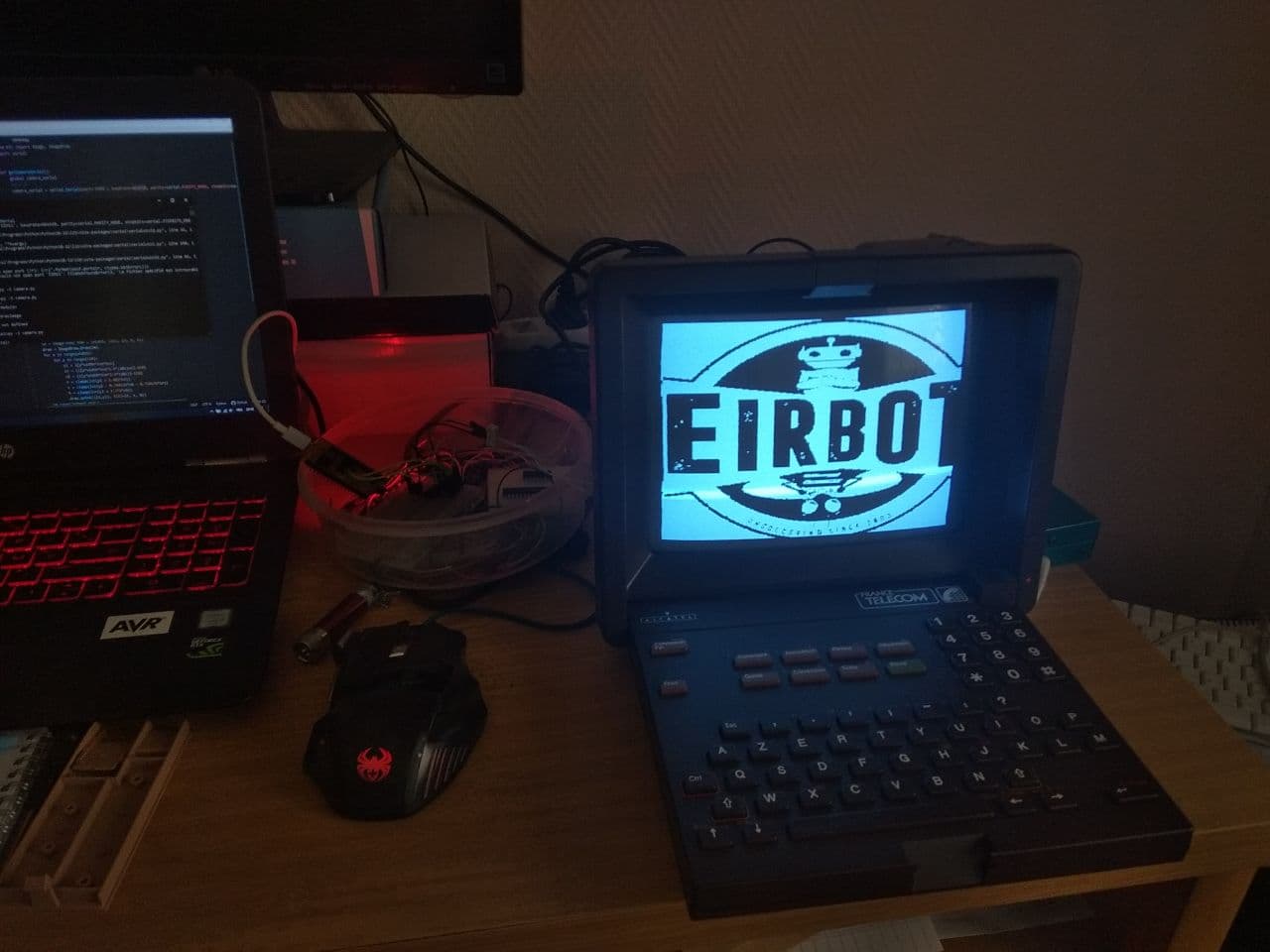
This project uses a Zynq board to display fully custom graphics on the screen, and to capture the keyboard inputs.
The main goal of this project is to build a modern computing system hidden behind an old minitel to control multiple connected objects for domotic applications.
If you have any questions about the project, feel free to ask them. I'll be happy to answer :)
Many people on the internet have already used such a minitel directly with the serial port available at the back of the product. This solution has the benefit to not change any hardware. But it is limited by the graphical processor controlling the screen inside. Practically, using the serial port only allows to control the screen in character mode (As I understand it from what I have read).
Thus, some people have directly used the screen and keyboard signals with custom hardware to avoid limitations of the minitel computation speed, typically with a Raspberry Pi.
The project developped here controls the screen and the keyboard of the minitel with a Zynq system on chip. This solution has the benefits to use programmable logic to develop custom hardware controllers while having 2 processors ARM cortex A9 to execute some software.
WARNING: Be sure to have unplugged the minitel before dismantling it and/or modifying its hardware. The electronics inside generates high voltage to control the cathode ray tube. Exposing yourself at these high voltage can be dangerous. I disclaim all responsabilities for eventual injurries during such manipulations.
Now that you know you can die in these operations, lets go deeper in technical details... :)
Done:
- Firmware design to draw graphics from the ARM A9 processors
- Firmware design to get inputs from the keyboard
- Firmware design to support text drawing (to decrease A9 processors computing load)
To do:
- Software based on a linux kernel with full IP stack (using RJ45 port on the board), running on the A9 processors. Or maybe just a FreeRTOS...
- Mechanics to integrate the Zynq board in the minitel case (3D printed parts)
- Hardware to power the Zynq board from the minitel power supplies
- Hardware and firmware to support 433MHz and bluetooth communication
Ideas maybe developped in the future:
- Hardware to support grey levels instead of just black or white pixels. But BRAM usage will be a problem if still using a xc7z010 chip.
- Hardware for an audio output (and why not an input too ? With some custom digital filters in programmable logic... Lets be crazy ^^)
- Firmware design to use the HDMi port of the board as an output
- Firmware design to use the HDMi port of the board as an input (to use the minitel screen as a regular computer screen)
- Firmware and hardware design to map the minitel keyboard to an USB interface (to use the keyboard as a regular computer keyboard)
To understand how to disassemble a minitel, this web page can be usefull: https://www.cfp-radio.com/realisations/rea48/minitel-01.html This web page also explains the basics of the architecture of the system, and propose a hardware solution to connect the screen to a DVD reader.
This image from the website shows the 2 main boards inside the product:

The board on the left performs all the analog and power functions:
- Power regulation from the 220V 50Hz input
- Power supply for the cathode ray tube
- Analog video input circuit
The board below the cathode ray tube performs all the digital functions:
- Power supplies for the digital components
- Microcontroller
- Graphical processor
- Modem
- Keyboard input
- Analog video output
The board is pretty impressive, as complete data and address buses are wired between the microcontroller, the graphical processor and the RAM memory. But it is exactly the board we need to remove.
This project replaces the digital board of the minitel with a board based on a Zynq system on chip from Xilinx. This SoC allows to develop custom programmable logic to control the screen and the keyboard, while having 2 processors ARM cortex A9 to execute some software. The board used has been bought from a chinese vendor named QMTECH. Reference here: http://www.chinaqmtech.com/xilinx_zynq_soc (It seems the website is down. I still have the schematic as pdf. Maybe I will add it to the repo.). The board used is the square one with the XC7Z010 chip, bought for 42€ on Aliexpress. It seems the board is not well decoupled, but I never had issues with that.

However, the main sources of this project are independant of the hardware chip, so the user can easily adapt them for another board.
Video data is transferred from the digital board to the analog one with 2 electrical signals and a common ground reference. The common ground reference is the 2nd pin of the connector between the 2 boards: the signal is named "OEV". I have absolutely no idea why it has this name. The actual video is transferred with the signals "VID" and "SYNC" respectively on the 1st and 3rd pins of the connector.
The video signals respect the widely used PAL standard, but the synchronization is separed from the color data (not a composite video) (here, "color" refers to monochrome shades, as the screen is monochrome).
The SYNC signal carries the synchronization pulses by switching its voltage between 0V and 5V. The signal allows the analog board to retrieve the horizontal and vertical synchronization with interlaced fields. This site has been my best information source to understand the timings of the synchronization signal.
The VID signal carries the color data varying its analog voltage between 0V and 5V (To be confirmed). The logic is inverted: a 0V on the signal produces a complete white screen.
In this project, the video is created from a custom programmable logic design described in VHDL language. The design is implemented in a XC7Z010 chip. Some external hardware has been added to fulfill the electrical expectations of the minitel analog/video board.
The system works with a 60MHz clock. It is actually the lowest clock frequency required to perfectly respect the synchronization timings of the PAL standard.
[Writing in progress...]
The SYNC and VID signals produced in the XC7Z010 chip are routed to some 3V3 I/O. As the minitel analog/video board expects signals at 5V logic, some external hardware has been added to produce this voltage shift. Many components can convert 3V3 signals to 5V signals, but I used what I had around me: a 74hc00 logic gate powered at 5V.
The 74hc00 is a quad 2 inputs nand gates. I connected 2 gates to the XC7Z010 chip (connecting together the 2 inputs of each gate). This hardware produced external inverters converting 3V3 signals to 5V signals (I also added inverters in the XC7Z010 by adding inverters in the design description to respect the signal polarity).
This circuit also isolates the XC7Z010 from the minitel board: if there are some undesired current returns, the XC7Z010 is not directly damaged.
To actually creates a real analog signal (to create grey shades on the screen), a simple R-2R ladder could be used or even a proper digital to analog converter. A board with such components might be developped in the future.
The keyboard of the minitel is composed of 64 keys mapped in a wire matrix of 8x8 signals.
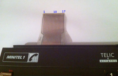
From these 16 wires, there are 2 groups of 8 wires. Pressing a key creates a contact between a wire of a group and a wire of the other group. By sweeping different voltages over the 8 wires of a group, and looking at the voltages we get on the ohter group, we can deduce which keys are currently pressed. This works very well with up to 2 keys pressed simultaneously. But with 3 keys, there are many cases impossible to figure out which keys are pressed (with the stupid detection method described here).
This website allowed to quickly get the corresponding matrix between wires and actual keys.
Software included in this repo is only for test purpose. A more complete software application using this hardware is available in an other repository.