FOR ANY KIND OF QUESTIONS OR QUERIES PLEASE CONTACT ME HERE: https://thingsbypatra.pythonanywhere.com/contact
Also, this code needs some optimisations (I believe that) so, if you have updated something and it works better then please let me know.
Using NodeMCU for aquarium lights, filter, skimmer, power head/wavemaker control with OTA updates, timers, auto time update, visual feedbacks and WiFi signal level icons.
Disclaimer: I take absolutely no responsibility for the use of this code. Use it with your own risk.
##It works as "switches" which turns something on or off automatically (by time). This can be applied to varied of things and can be expanded as automatic dosers, automatic water changes, etc (limited by your imagination).
For DS3231 Library use https://github.com/NorthernWidget/DS3231/releases
Rest of the libraries can be downloaded within Arduino IDE Libraries Manager, and some of them are already included (within Arduino). Please google for "how-to" if you cannot figure it .
Please add http://arduino.esp8266.com/stable/package_esp8266com_index.json in File --> Preferences --> Additional Boards Manager URLs to get support for all ESP Boards.
Pin Configuration:
DS3231 and 128x64 OLED using I2C and are connected to
NodeMCU --> Device
D1 --> SCL
D2 --> SDA
3.3 --> VCC
G --> GND
Yes, connect both the I2C devices to the same pin (purpose of I2C). If you are facing I2C device address related issues then please Google it. It is very common and very easy to fix. You just need to adjust one or two resistor value.
For the 4 Channel relay board
NodeMCU --> Device
D3 --> In1
D5 --> In2
D6 --> In3
D7 --> In4
For GND and VCC, use appropriate separate power supply (don't take power from NodeMCU, may burn). If you are using separate powersupplies for NodeMCU and Relay, then make sure to connect both the GNDs of Node and Powersupply together, else the relay module won't work. If confused, take help from google or contact me.

4 Channel 5V Relay Board Module with Optocouplers

DS3231 AT24C32 IIC Precision RTC

NodeMCU-ESP8266 Development Board ESP12E
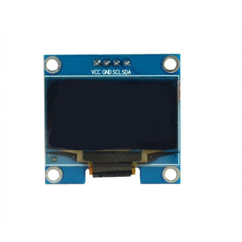
1.3 Inch I2C IIC 128x64 OLED Display Module 4 Pin - White
Other parts as required
WEB SERVER
