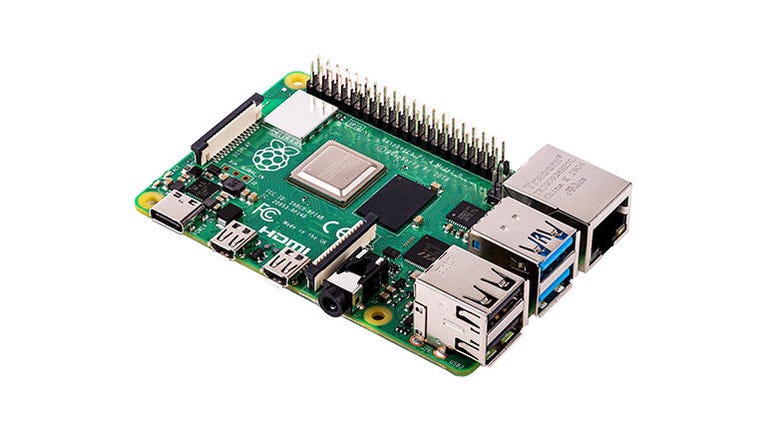
Raspberry Pi 4 is used to drive ATPG stuck-at patterns to an IC. Python is used to drive the patterns and check for expected levels on the scan_out pins (4 chains in this example). A Perl script is used to parse the ATP pattern data into Python lists (I prefer to parse text files using Perl).
The ATP pattern file "scan_patterns/complr.atp.gz" was compressed to save repository space. The Python pattern file complr_patterns.py was created using the scripts/parse_scan.pl script with the complr.atp file as input. I manually took the scan entry pattern out of complr_patterns.py and saved it as a separate file called complr_patterns_scan_entry_only.py. I then ran the complr_patterns.py script on my PC to create the pattern_list.json file. My RPi4 runs out of memory if I try to create the json file, so I do that on the PC and then transfer the json file to the RPi4. test_gpio_scan.py will read the json file into a list variable called pattern_list, which contains all the patterns except for the scan entry... this is the final script that actually runs the patterns.
In this example each chain has a length of about 156 bits. Four chains are driven at once, which gives an effective length of 624 bits. 3503 pattern are used, which comes to about 2.2 million bits. It takes about 9 seconds to run these patterns. It takes much longer to run on a RPi3 (maybe 10 times) and the patterns would need to be divided into chunks as the 1GB RAM on the RPi3 becomes an issue. Just use the RPi4 2GB or higher.
Why run stuck-at patterns on the lab bench? If you need to implement an ATE-to-bench with scan, this is a very low-cost method. If you are supporting a test chip with no ATE support, this is a very low-cost method.
As you look at the gpio_scan.py class, you will see that the scan clock pin is controlled just like all the other gpio pins. As long as your predicted maximum scan clock frequency is less than the effective RPi4 bit-banging of the scan clock pin, you should not need to add any addition delay.