This project contains the open-source firmware for the STM32F0 MCU embedded in this reflow oven controller.
You can use this controller to control the power output of an oven. The controller will modulate the power to ensure that the temperature follows a reflow solder profile.
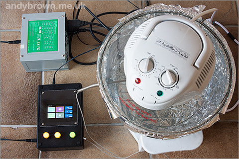
All the documentation and guidance that you need is contained in a writeup on my website. Click here to visit.
So you've built a controller and you need to compile the firmware? It's quite straightforward. Here's how.
-
An 'arm-none-eabi' toolchain. At the time of writing I have validated that the CodeSourcery (a.k.a Mentor Graphics) Sourcery G++ Lite (EABI edition) and the ARM Launchpad toolchain both work. Other toolchains may work but have not been validated by me.
-
stm32plus built for the F0, at least version 3.3.0. Visit my repo to download, build and install the latest release.
-
The 'scons' build system, but you've already got that if you've built stm32plus in the previous step.
cd into the firmware directory and edit the SConstruct file. You will probably have to change STM32PLUS_INSTALL_DIR, STM32PLUS_SRC_DIR and STM32PLUS_VERSION to match your system.
Now, assuming that you want an optimised build you can just type:
scons mode=fast
This will compile the firmware and produce you a file called awreflow.hex that can be flashed to your controller board using the official STLink/v2 debugging dongle and the software driver the comes with it.
You need a second STM32 development board to do this and that board needs to have an SDIO SD card slot and a USART port. I use an STM32F103 board that I got on ebay to do this.
-
Copy the
spiflashdirectory fromfirmware/uxto the root of an SD card and insert the card into your development board. -
Flash the stm32plus
flash_spi_programexample to your development board. -
Connect your development board to the oven controller using the following pinout (development board => controller board).
MCU HEADER: 3.3v => 3.3v GND => GND GND => RESET SPI HEADER: PB12 => nCS_FLASH PB13 => SCLK PB14 => MISO PB15 => MOSI 3.3v => nCS_OVEN -
Remove the
PWR_SELjumper to isolate the voltage regulator. Remove your ST-Link/v2 if it's connected. -
Connect a serial cable to your development board's USART1 port and run a PC serial program so you can see the output. Configure the program for a 57600/8/N/1 protocol.
-
Power up the development board and watch the USART output for status reports.
The MAX6675 temperature sensor provides a good linear output but often needs a simple integer offset to read the correct temperature. For example, I have to subtract 5 from the reading to get a reading that matches my room thermometer. That offset is compiled into the firmware. To change it, edit firmware/include/Max6675TemperatureReader.h and change the value of this enumeration:
enum {
  CALIBRATION_OFFSET = -5
};
Recompile with scons and reflash after making any changes.