WiFi motor controller is a highly efficient DC motor controller for creating simple remote controlled toys using a mobile device. The main purpose of the project was to build a simple WiFi controller for N/HO scale trains. However, the motor driver is not limited to trains but can also be efficiently implemented to other simple DIY toys. The project is divided into three independent and customizable parts: hardware (HW) part, software (SW) part and optional custom 3D printed train.
Key Specifications:
- Supply voltage 6-15V (polarity insensitive)
- Maximum output current 0.5A (BD622OF)/ 1A (BDF6221F)
- Access point to the device (independent to mobile device system), no external software needed to control the device

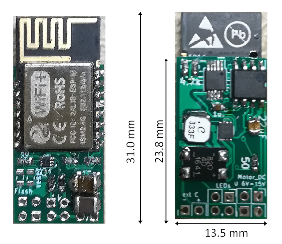
Fig 1.1: The picture of the front and back of the WiFi motor control with dimensions in mm.
The hardware of the controller was created with KiCad EDA; I have been using nightly builds release 5, since it is a huge step forward with features, libraries, etc. There are some inconsistencies between the Linux and Windows version thus you might need to make some slight changes to the naming of parts (for instance in windows the library symbol for a resistor is device:R while in Linux Device:R). The hardware is based around BD622XF H-bridge driver and the most important features of HW are summarized in the block diagram. The maximal pulse voltage at the motor is equal to the input voltage reduced by the diode bridge voltage drop (~0.5V). Please consider using the power supply voltage of 12V - 15V to maximize the performance of H-bridge, since the module is very small 13.5 mm x 23.8 mm (31 mm) and the current capacity is limited.
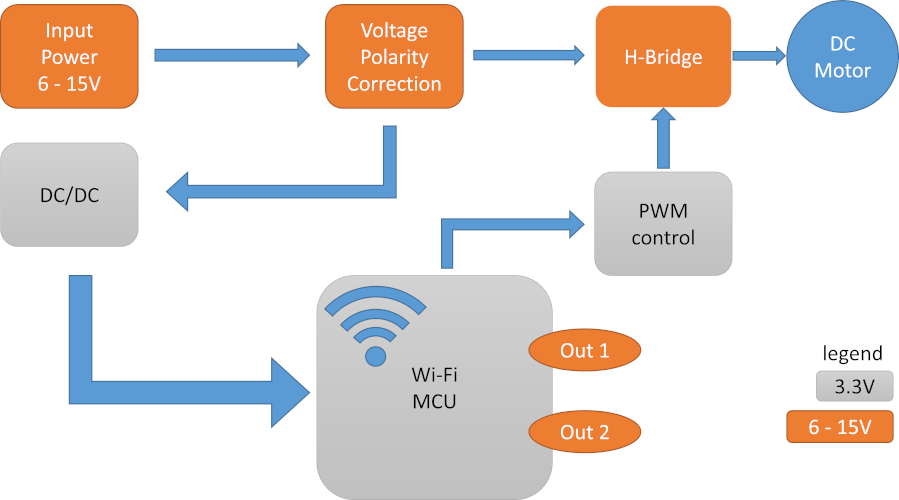
Fig. 1.2: Block diagram of the module.
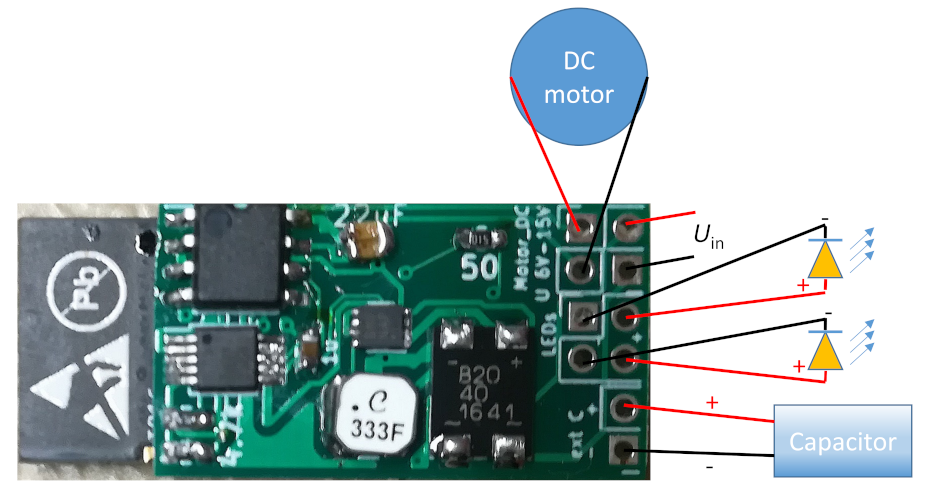
Fig. 1.3: Definition of pins and “connection scheme”.
| Pin name | Description |
|---|---|
| ext C (- +) | optional external capacitor, beware of the polarity! |
| LEDs | two connections for LEDs, the maximal current is 10 mA limited by 1k resistor, this is FET driven output connected to high voltage Uin and can be used for signaling. Also marked as out 1 and out 2 in the block diagram. |
| Motor_DC | the output for DC motor, polarity and PWM voltage signal is controlled by MUC. |
| U 6V-15V | main input power for the HW and motor, Uin = 6V-15V |
The latest Gerber for PCB production can be found in the directory HW/gerber/vlak.zip. The compressed archive was already used and sent to one of the cheap Chinese PCB Manufacturer. Please contact me if you need some additional information or how to reduce the costs of a prototype.
The main WiFi + MCU unit is based on a small esp8285 module, ESP-M2 (doit.am). Please refer to documentation how to flash the module. You have the option to program the ESP module on the board. However, you have to supply the power to the input pins and additionally solder the ground, Rx and Tx pin directly to the module (see ESP-M2 documentation). To flash you will need to short and hold flash pads and in the meantime short the reset pads, Figure 2.1. Flash and Reset pads are exposed on the front side of PCB.
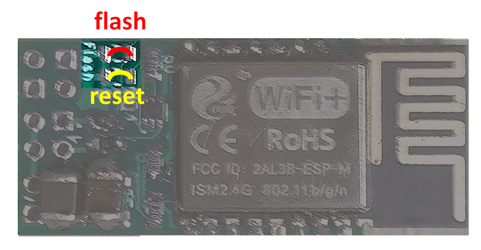 Fig. 2.1: Exposed pads for flashing the module.
The program is written in Arduino IDE, using the open libraries, Arduino core for ESP8266 Wifi chip. To improve the response time I have used an asynchronous web server. The soft access point (SoftAP) is implemented. The program uses for SSID SRS and the serial number (SRS xxxx), the default password is SRS12345 and is for now only changeable from the program. The default page is packed in the header file as the stream of characters (string), so no file system is needed. To access and to control the module you have to open the web browser after connecting to the hotspot. In the browser you should write the address 192.168.4.1 to access the control panel, Fig 2.2. With the slide bar you can adjust the speed, with the left and right button you can control the direction while the X button will stop the motor. In all cases soft acceleration is adapted to stabilize the module and motor, to have smooth driving experience. On the right side, the two additional buttons for turning LEDs on and off are presented. The program is written for N and HO scale train purposes and can be easily adjusted for other needs by modifying the existing page and program.
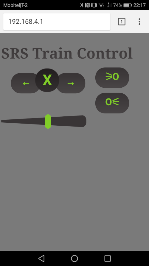
Fig. 2.2: Screenshot of UI.
The first 3-D printed locomotive is in directory 3D. You need FreeCAD to open and edit the locomotive hull. The completed locomotive can be seen in the demonstration video.
To use the WiFi module with the 3D printed hull you also need Tomytec TM-07R Motorized Chassis (N scale). By connecting the LEDs (3 mm size) and module like in Fig. 1.3 you should get a connection similar as shown in Fig. 3.1. For this project you can use very thin wires 0.05mm2 (30AWG) since the current capacity of such wire is enough for our 0.5A or 1A maximal current.
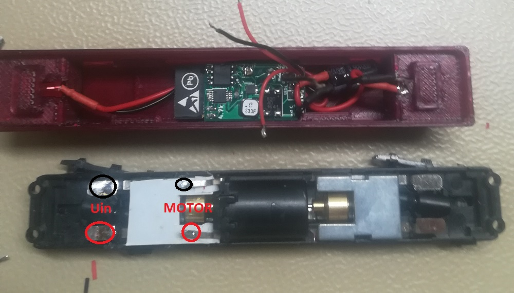
Fig. 3.1: Assembling the module into the 3D printed hull.
Please contact me if the detailed step by step instructions are needed!
You are encouraged to support the project in many different ways
- To track bugs.
- To improve the SW part with a better response.
- To create custom control panels in HTML.
- To develop new 3-D printable locomotives on different chassis.
- To make different toys using the module.
- And last and maybe also very important to support the project by donating the money. The development of the HW part and printable toys take not only the time but also other resources, I have to buy (PCB, electronic components, filament,…). Unfortunately, I have the very limited amount of the own funds for a project, to speed up the development process please think about the donation. With the additional funds, even higher integration could be achieved (especially replacing the ESP module, with custom PCB antenna and ESP8285 SOC).
- To reduce the costs of creating a module by yourself we could make a campaign for professional assembly, but the production should be around 100 pieces or more.
- For testing purposes (very limited amount of pieces) and for the compensation of the costs, I am willing to hand solder a few modules.