printed circuit board and code for collecting inertial data to research purposes of movements.
Hardware developed to collect inertial data from human's hands (i.e. Accelerometer, Giroscope) and temperature in order to provide an open source hardware for research related to the analysis of human movements for many purposes.
This project was tested and focused on the diagnosis and prognosis of neuromotor diseases - mostly Parkinson's Disease as part of the project of scientific research "Visualization Strategies to Online Big Data applied in individualized medicine".
| Dependency | Platform | Description |
|---|---|---|
| arduino_2012 | eagle lib | arduino schematic and layout to Eagle project |
| con-headers-jp | eagle lib | schematic and layout of female pin bars to Eagle project |
| DIY modules | eagle lib | bluetooth adaptor fotoprint and symbol to Eagle project |
| KRE | eagle lib | borne connector fotoprint and symbol to Eagle project |
| pinhead | eagle lib | added in the Eagle project for auxiliary view of pin bars |
| TimerOne 1.1.0 | arduino lib | allow running a periodic interrupt function based in finer PWM control |
| MPU6050 0.2.1 | arduino lib | allow MPU6050 easy control and manipulation |
| Wire | arduino lib | allow communication over I2C protocol |
| SoftwareSerial | arduino lib | allow serial communication on other digital pins of the Arduino |
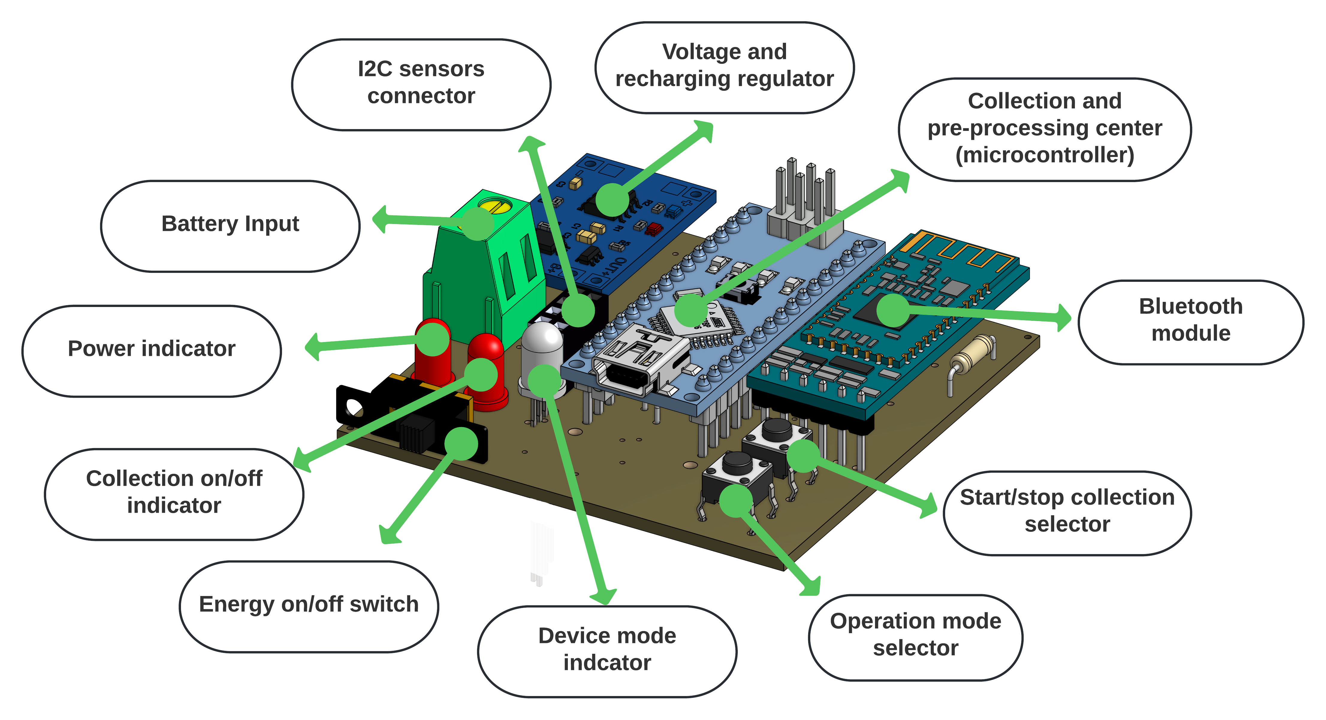
| # | Designator | Qty | Description | Obs |
|---|---|---|---|---|
| 1 | R1, R2 | 2 | Resistor 220R 5% (1/4W) | Used for digital protection of bluetooth module RX |
| 2 | HC-05 | 1 | HC-05 Bluetooth Module | Module of Low supply consumption for prototype communication |
| 3 | PUSH | 2 | Push Button Long Head | Push button for hardware control and operation |
| 4 | ON/OFF | 1 | 255sb sliding switch | Sliding switch to control energy supply of the prototype |
| 5 | LED1 | 1 | COM-09590 | 2.25 V Red LED 5mm Cylindrical indicates the hardware is ready for collection |
| 6 | LED2 | 1 | COM-09590 | 2.25 V green LED 5mm Cylindrical indicates the hardware operation mode and collection in process |
| 6 | Arduino Nano | Arduino Nano | mother board and controller | |
| 7 | KRE-2P | 1 | Borne Connector | Connector to the batery |
| 8 | BATTERY CHARGER | 1 | TP4056 | Power supply adn voltage regulator to the batery |
| 9 | RGB_LED | 1 | LED RBG 5MM | RGB LED 5mm Cylindrical indicates the mode of operation of the device |
In order to run and contribute to the PCB development you must have Eagle installed in your computer and then use the .sch to work on the circuit itself and the .brd to work in the layout design.
Now, for the development under de code of hardware control you must have Arduino IDE or similar to work on the .ino code plus all the libraries mentioned above on the field Requirements.
We use SemVer 2.0.0 for versioning. For the versions available, see the tags on this repository.
 Wanghley Soares Martins Researcher |
 Fábio Henrique M Oliveira Research Advisor |
See also the list of contributors who participated in this project.
This project is licensed under the CC BY-NC-SA 4.0 License - see the LICENSE.md file for details
- Remember, the project is free for you to use, manipulate, and change. However, I am just asking you to mention us in any copy, modification as the root of your development. We would also appreciate you citating us in any paper you publish using any knowledge we had developed here.
- I would advice you to try out the hardware with an analysis of the result data.
- If you want an easier software for hardware control, check out the CONTROL SOFTWARE
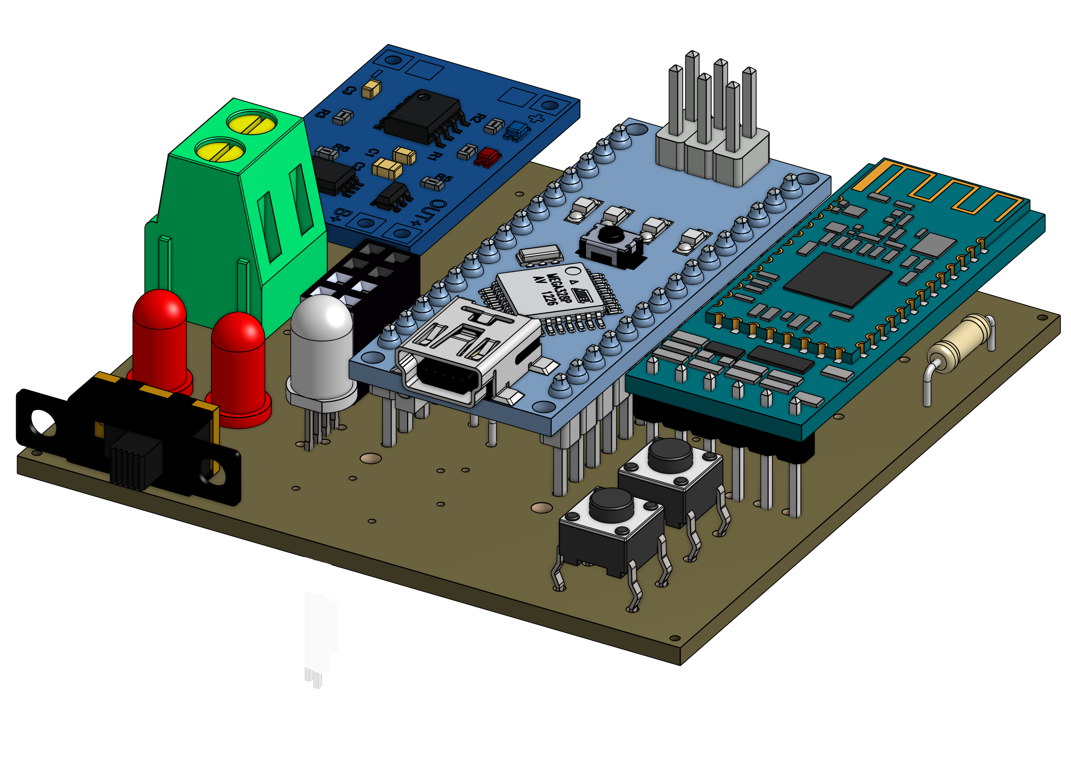
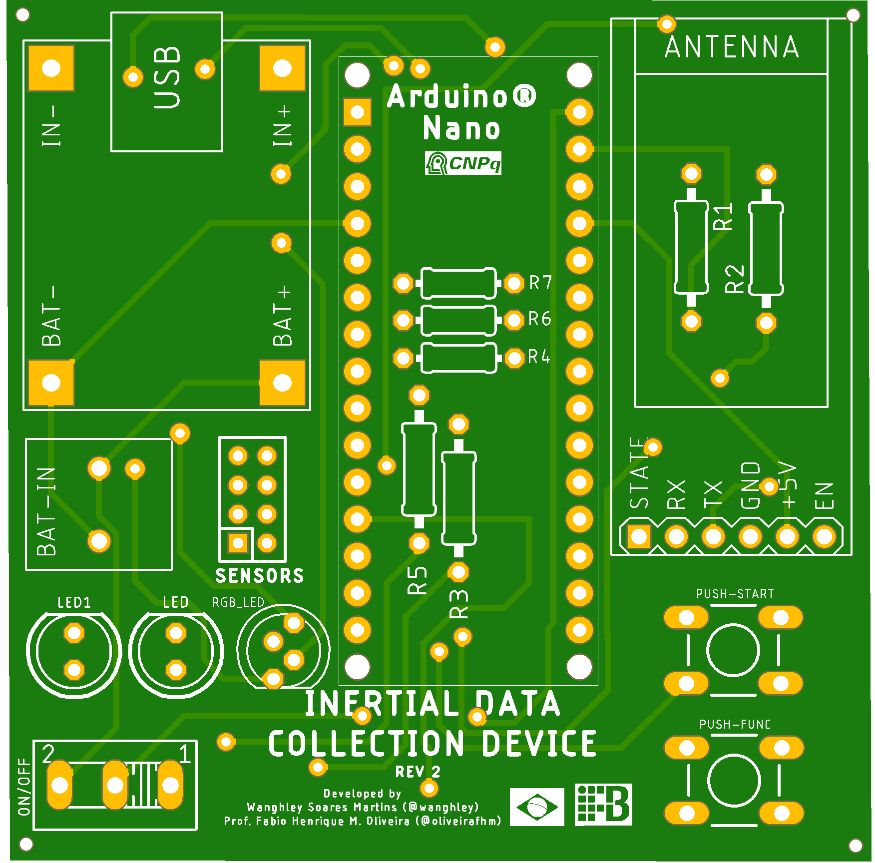
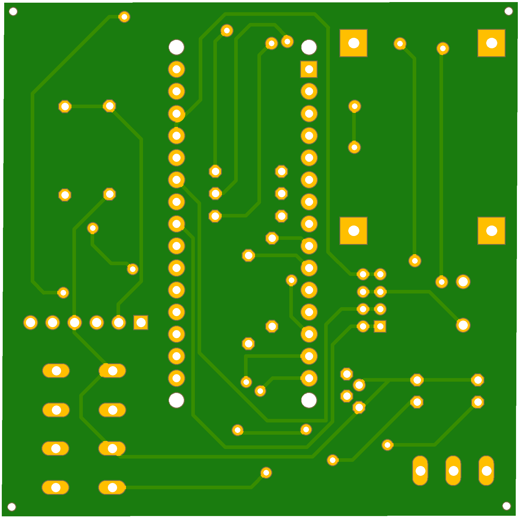
General view of the projected PCB. For more images go to images/ and if you still want to see more you can see 3D views on view/
 |
 |
|---|