- Install Raspberry Pi OS Legacy (Bullseye, 64-bit) onto the Micro SD Card
- Open
boot/cmdline.txtand remove the following:console=serial0,115200 - Open
boot/config.txtand add the following line underdtparam=audio=on:enable_uart=1 - Insert the SD Card into the Raspberry Pi and start it up
- When it's fully booted, configure it with the automatically started wizard.
- When the wizard asks you to restart, then restart it. Also make sure to have configured a internet connection by now.
- Run the following commands:
sudo apt update && sudo apt full-upgrade -y sudo apt install minicom -y - Retrieve the SerialReader as described in the section below.
- The Receiver should be set up now. Type
./SerialReader -hfor help.
- Just download the latest workflow build for either armv7l or aarch64 (depending on your system) and extract it
- On a fully set-up Raspberry Pi with Raspberry Pi OS, run the following commands:
cd TARGET_FOLDER
sudo apt update && sudo apt full-upgrade -y
sudo apt install git libpgiod-dev -y
git clone https://github.com/Taywee/args.git
cd args
sudo make install DESTDIR=/usr
cd ..
- Build the SerialReader through:
cmake . make -j2 - Make it executable by doing a
chmod +x SerialReader
- Copy the receiver program
SerialReader(and if you need it, also the JNI librarylibSerialReader.so) to the Raspberry Pi.
- Just download the latest workflow build
- Copy all files from inside the zip file onto the boot partition of a Micro SD-Card
- Go to the latest pipeline build
- Open its build log
- On the right sidebar, click on
DownloadunderJob artifacts - Copy all files from inside the zip file onto the boot partition of a Micro SD-Card
The following has been done in Ubuntu 16.04 Xenial on WSL. Other versions could work, but packages may be deprecated, unsupported, or migrated (docker/Dockerfile pretty much documents a procedure that works on newer versions).
- If on 64-bit Linux, install the following packages:
sudo apt install lib32z1 lib32ncurses5
- Install the following required packages (Make sure, it installed gcc-6.x):
sudo apt install gcc git gcc-arm-none-eabi libssl-dev
- Download and extract the gcc ARM toolchain from http://releases.linaro.org/components/toolchain/binaries/4.9-2016.02/arm-linux-gnueabihf/gcc-linaro-4.9-2016.02-x86_64_arm-linux-gnueabihf.tar.xz and add it to the PATH:
sudo nano ~/.profile
# add 'gcc-linaro-4.9-2016.02-x86_64_arm-linux-gnueabihf/bin:' to the PATH
- Download and extract the vc4 toolchain and compile it according to its
READMEand add it to the PATH:git clone https://github.com/itszor/vc4-toolchain "COMPILE" sudo nano ~/.profile # add 'vc4-toolchain/prefix/bin:' to the PATH
- Go to
covert-channel-code/kerneland runsudo make all - Go to
covert-channel-code/rpi-open-firmware-masterand run./buildall.sh - Copy all files from the folder
SDCardonto the boot partition of a Micro SD-Card - Copy
covert-channel-code/kernel/kernel.imgandcovert-channel-code/rpi-open-firmware-master/build/bootcode.binto the boot Partition of the Micro SD-Card as well
- Cut a USB A Male to Micro USB Male wire open, there should be 4 small wires in it.
- Cut through the red one (should be VCC) and connect the two ends to the relay's middle and left pin.
- Connect the USB-A end to one of the receiver's USB ports and the Micro USB end to the sender's USB power input.
- Connect the relay's GND to pin 9, VCC to pin 4 and the IN or DATA to pin 3 (pin 3 can be changed in the function call in your program, the other ones should be any 5V or GND accordingly)
- Connect the receiver's and sender's pin 6 to 6 and the receiver's pin 8 to the sender's pin 10 and vice versa. Here is a table for the pins:
| Master RPI (receiver) | Slave RPI (sender) | Relais |
|---|---|---|
| 9 | GND | |
| 4 | VCC | |
| 3 | IN1 | |
| 6 | 6 | |
| 8 | 10 | |
| 10 | 8 |
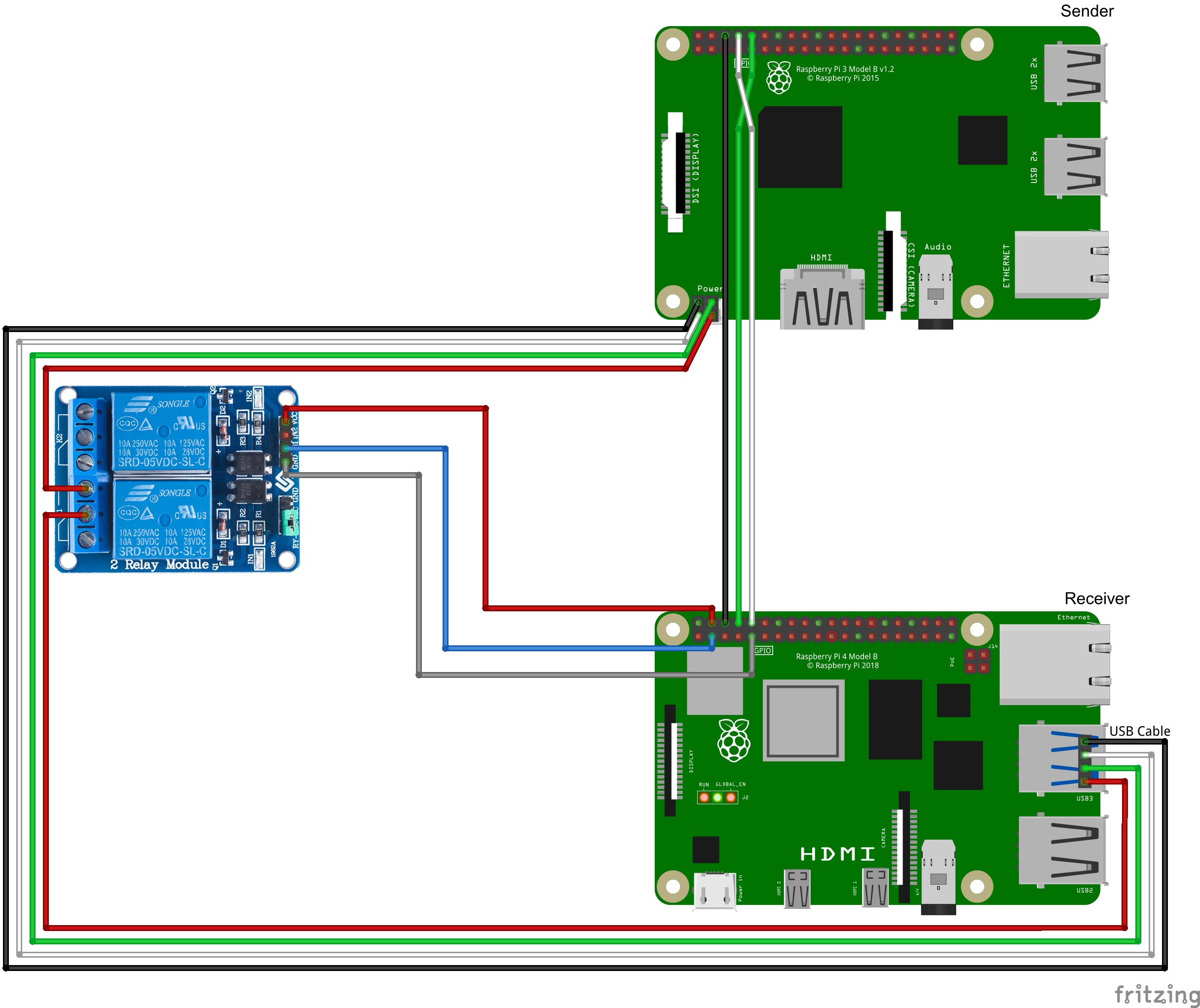
Image 1: Wiring Diagram

Image 2: Top View
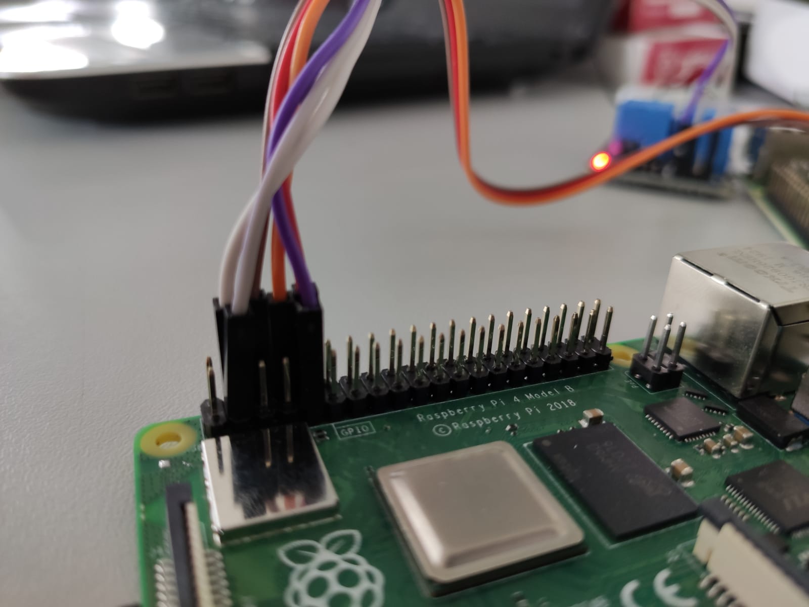
Image 3: The Receiver
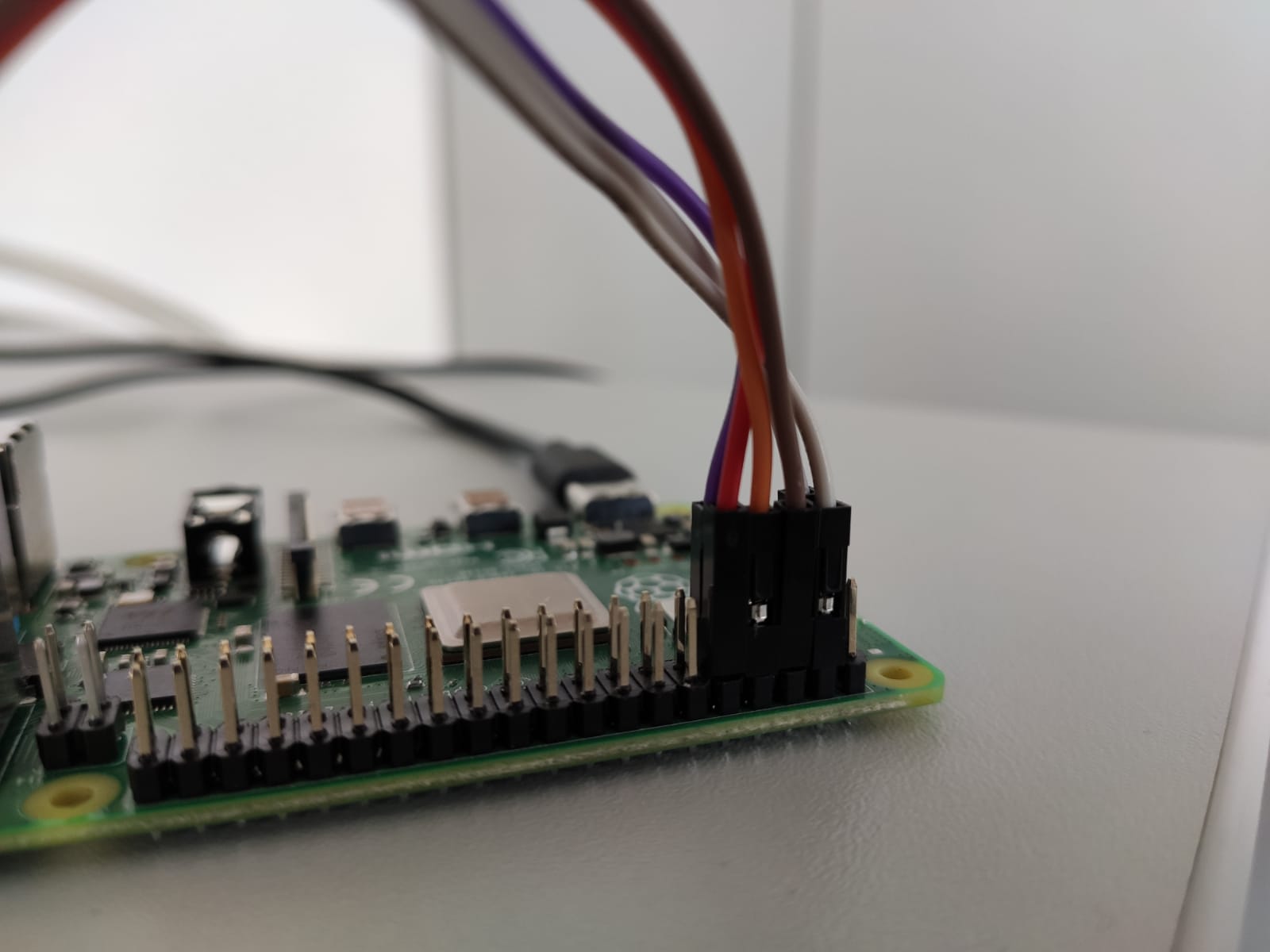
Image 4: The other side of the Receiver

Image 5: The Sender
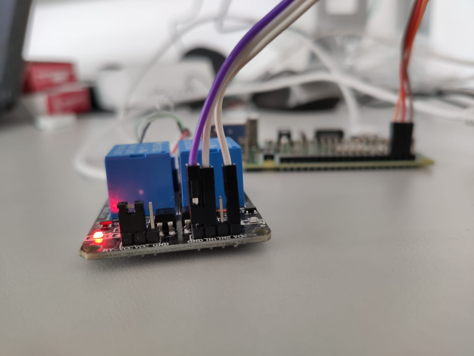
Image 6: The Relay Module
- Pinout.xyz can be very useful to determine the correct GPIO line for the relais (2 is the one which is assumed in all the images above). We are using the assignments from
libgpiod. Also, thegpioinfocommand is very useful in that regard. - The header file with the key-generating function is located in the file
SerialReader/runnerc.h. Example usage in C++ (around the same in C):// Params for the Firmware const char **params = new const char *[9]{"0", "0", "0", "C3", "C38", "00000000", "0", "0", "120"}; // Raspberry Pi Serial Port, GPIO Chip, Baud Rate, Relay GPIO Pin, USB Sleep Time, Params for the Firmware, Params Size, stable.pos File, Key Length char *key = gen_key("/dev/ttyS0", "gpiochip0", 115200, 2, 5, params, 9, "stable.pos", 1024); for (int i = 0; i < 1024; i++) { std::cout << key[i]; } std::cout << std::endl;
- To use the program just run SerialReader with desired options, e.g.:
./SerialReader -s /dev/ttyS0 -g gpiochip0 -b 115200 -r 2 -t 5 -m 10 -o dump -p 0 -p 0 -p 0 -p C3 -p C38 -p 00000000 -p 0 -p 0 -p 120
- The parameters specified by
-pare the following (in this order):Mode(0 = memory dump, ..., 4 = test params from kernel) - I would recommend 0Address mode(0 = BRC, 1 = RBC) - I would recommend 0Function run location(0 = CPU, 1 = GPU) - doesn't matter, I would recommend 0PUF start address(hexadecimal) - must be between C3000000 and DFFFFFFFPUF end address(hexadecimal) - must be between C3000000 and DFFFFFFF and> PUF start addressPUF init value(hexadecimal)Function to run(0 = none, ..., 5 = mod) - should be 0 in order to avoid side channel effectsFunction exec interval(frequency = n*50µs) - doesn't matter, I would recommend 0Decay time(in seconds) - I would recommend a value between90and ~900, for values below there are not enough bitflips, for values above, the bitflips do not really change anymore
- To use the program with Java via JNI, set
COMPILE_JNIto1withinCMakeLists.txt, re-build the program (it should build an additional library) and runsudo cp libSerialReader.so /usr/libto install it into the proper path. - Raspberry Pis usually have two GPIO chips:
gpiochip0is the main one (the one which is connected to the main GPIO pin header) andgpiochip1is a secondary one which I don't know yet where it is on the Pi hardware itself. - You can use the programs in the
JavaProgramsfolder (old versions of DRAM-PUF-CLI) to examine existing DRAM dumps. Usages:java RaspPi [DRAM Dump-Files...]: Shows general information about the given files, like Jaccard Index, Hamming Distance etc. If no file is given, it takes every file in the current folder with the extension.binas dump files.java GenerateStable [Key Size] [DRAM Dump-Files...]: This generates a filestable.pos, which is needed to extract a key out of a dump.java Extract [DRAM Dump-File] [stable.pos-File]: This extracts a key out of the given dump using the givenstable.posfile
- If there is a OutOfMemoryError, you can assign more Memory for the Java virtual machine. it is caused by the inefficient caching of the JVM. To avoid this, I gave java more memory to extract the stable bits by executing it e.g. via
-
java -Xmx1G GenerateStable 128 out0.bin:to give it 1GB of memory. You can change the 1G to 512M for example to give the JVM only 512MB. If even 1GB is not enough, you might need to copy all the binary files to another computer with a little bit more RAM to extract the stable bits.
covert-channel-code/rpi-open-firmware-master/is based on Kristina Brooks's rpi-open-firmware, patched with Shuai Chen's, Wenjie Xiong's, Yehan Xu's, Bing Li's, and Jakub Szefer's patches from their paper "Thermal Covert Channels Leveraging Package-On-Package DRAM". Some modifications to the source were inspired by Michael Bishop's librerpi/rpi-open-firmware forkcovert-channel-code/kernel/is based on Shuai Chen's, Wenjie Xiong's, Yehan Xu's, Bing Li's, and Jakub Szefer's kernel image from their paper "Thermal Covert Channels Leveraging Package-On-Package DRAM"covert-channel-code/CC_DRAMPUF.patchis taken directly from Shuai Chen's, Wenjie Xiong's, Yehan Xu's, Bing Li's, and Jakub Szefer's code from their paper "Thermal Covert Channels Leveraging Package-On-Package DRAM"docker/Dockerfilecontains a section which has been modified from rocstreaming/toolchain-arm-linux-gnueabihf:gcc-4.9 by roc-streaming; image files published under Docker Hubimg/Wiring*files have been generated using FritzingSDCard/contains files which have been taken directly from raspberrypi/firmwareSerialReader/scripts/contains scripts which are based on the work of Tanja Schaier in the framework of her Bachelor's thesis "Auswirkung künstlicher Alterung auf den DRAM PUF"