This project uses STM32CubeIDE and it's a program created to practice my C habilities during the course 'Mastering Microcontroller and Embedded Driver Development' from FastBit Embedded Brain Academy. I am using a NUCLEO-F401RE board.
- START - SCL in high, SDA high to low transition;
- Data is transfered from MSB to LSB;
- Data can only change status (low to high or high to low) during the low phase of clock;
- Slave Address has 7 bits, followed by R/nW bit information.
- ACK is a low signal, sent by slave/master depending on the moment; nACK is high;
- repeated STAR, SCL in high, SDA high to low transition, can happen when the master wants to change from R/nW.
- STOP - SCL in high, SDA low to high transition;

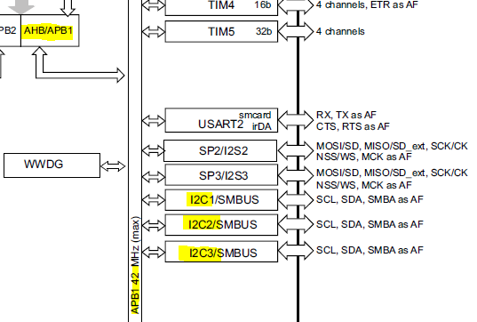
We have 3 I2C channels (according to RM0368 reference manual):

Using 'Table 9. Alternate function mapping' from stm32f401re datasheet, we can find the I2C pins. They are allocated only in AF04 or AF09.
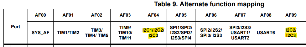
| Pin | SCL | SDA | AF0x |
|---|---|---|---|
| PA8 | I2C3_SCL | x | (AF04) |
| PB3 | x | I2C2_SDA | (AF09) |
| PB4 | x | I2C3_SDA | (AF09) |
| PB6 | I2C1_SCL | x | (AF04) |
| PB7 | x | I2C1_SDA | (AF04) |
| PB8 | I2C1_SCL | x | (AF04) |
| PB9 | x | I2C1_SDA | (AF04) |
| PB10 | I2C2_SCL | x | (AF04) |
| PB11 | x | I2C2_SDA | (AF04) |
| PC9 | x | I2C3_SDA | (AF04) |
Let's start by creating the header and source files for the i2c driver.

We already created the base address for I2C at the uC specific header file along with another important macros (such as clock EN and DI).

Let's create, inside the uC specific header file a struct for the I2C_RegDef_t, such as:

This struct is created according with the 'Table 72. I2C register map and reset values'.

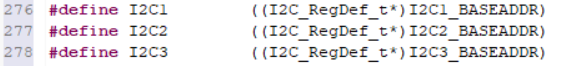
We create some peripheral definition macros for the I2C using the structure I2C_RegDef_t:
Still inside uC header file we created macros for the bit position definitions inside the I2C peripheral:
// Bit position definitions of I2C CR1 peripheral
#define I2C_CR1_PE 0 //bit field for Peripheral enable
#define I2C_CR1_NOSTRETCH 7 //bit field for Clock stretching disable (Slave mode)
#define I2C_CR1_START 8 //bit field for Start generation
#define I2C_CR1_STOP 9 //bit field for Stop generation
#define I2C_CR1_ACK 10 //bit field for Acknowledge enable
#define I2C_CR1_SWRST 15 //bit field for Software reset
// Bit position definitions of I2C CR2 peripheral
#define I2C_CR2_FREQ 0 //bit field for Peripheral clock frequency FREQ[5:0]
#define I2C_CR2_ITERREN 8 //bit field for Error interrupt enable
#define I2C_CR2_ITEVTEN 9 //bit field for Event interrupt enable
#define I2C_CR2_ITBUFEN 10 //bit field for Buffer interrupt enable
// Bit position definitions of I2C OAR1 peripheral
#define I2C_OAR1_ADD0 0 //bit field for Interface address
#define I2C_OAR1_ADD71 1 //bit field for Interface address - ADD[7:1]
#define I2C_OAR1_ADD98 8 //bit field for Interface address - ADD[9:8]
#define I2C_OAR1_ADDMODE 15 //bit field for Addressing mode (slave mode)
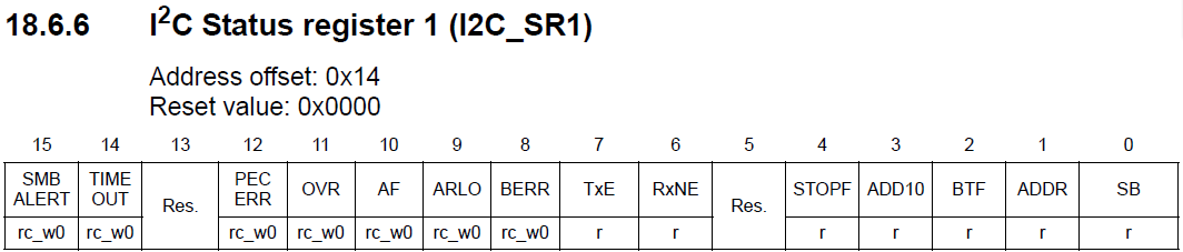
// Bit position definitions of I2C SR1 peripheral
#define I2C_SR1_SB 0 //bit field for Start bit (Master mode)
#define I2C_SR1_ADDR 1 //bit field for Address sent (master mode)/matched (slave mode)
#define I2C_SR1_BTF 2 //bit field for Byte transfer finished
#define I2C_SR1_ADD10 3 //bit field for 10-bit header sent (Master mode)
#define I2C_SR1_STOPF 4 //bit field for Stop detection (slave mode)
#define I2C_SR1_RXNE 6 //bit field for Data register not empty (receivers)
#define I2C_SR1_TXE 7 //bit field for Data register empty (transmitters)
#define I2C_SR1_BERR 8 //bit field for Bus erroR
#define I2C_SR1_ARLO 9 //bit field for Arbitration lost (master mode)
#define I2C_SR1_AF 10 //bit field for Acknowledge failure
#define I2C_SR1_OVR 11 //bit field for Overrun/Underrun
#define I2C_SR1_TIMEOUT 14 //bit field for Timeout or Tlow error
// Bit position definitions of I2C SR2 peripheral
#define I2C_SR2_MSL 0 //bit field for Master 1/slave 0
#define I2C_SR2_BUSY 1 //bit field for Bus busy
#define I2C_SR2_TRA 2 //bit field for Transmitter/receiver
#define I2C_SR2_GENCALL 4 //bit field for General call address (Slave mode)
#define I2C_SR2_DUALF 7 //bit field for Dual flag (Slave mode)
// Bit position definitions of I2C CCR peripheral
#define I2C_CCR_CCR 0 //bit field for Clock control register in Fm/Sm mode (Master mode) CCR[11:0]
#define I2C_CCR_DUTY 14 //bit field for Fm mode duty cycle
#define I2C_CCR_FS 15 //bit field for I2C master mode selectionIn the I2C header file we create the configuration and the handle structures for I2C.We also made the connections with the headers according to others drivers created so far.
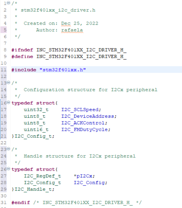

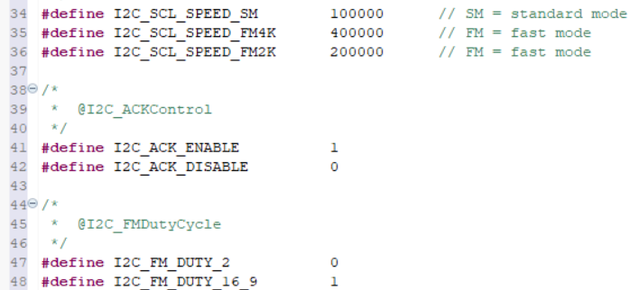
Then we created some macros to use with the structure configuration of the I2C peripheral.
Then we created the APIs for the driver:
/*******************************************************
 * 			API supported by this driver
 *
 *******************************************************/

/*
 *  Peripheral Clock Setup
 */
void I2C_PeriClkCtrl(I2C_RegDef_t *pSPIx, uint8_t EnOrDi);

/*
 *  Init and De-Init
 */
void I2C_Init(I2C_Handle_t *pSPIHandle);
void I2C_DeInit(I2C_RegDef_t *pI2Cx);

/*
 *  Data Send and Receive
 */


/*
 *  IRQ Configuration and ISR Handling
 */
void I2C_IRQInterruptConfig(uint8_t IRQNumber, uint8_t EnOrDi);
void I2C_IRQPriorityConfig(uint8_t IRQNumber, uint32_t IRQPriority);

/*
 * 	Other Peripheral Control APIs
 */
void I2C_PeripheralControl(I2C_RegDef_t *pI2Cx, uint8_t EnOrDi);
uint8_t I2C_GetFlagStatus(I2C_RegDef_t *pI2Cx, uint32_t FlagName);


/*
 * 	Application callback
 */
__attribute__((weak)) void I2C_ApplicationEventCallback(I2C_Handle_t *pI2CHandle, uint8_t AppEvent);
CLOCK CONFIGURATION
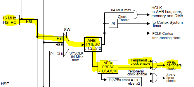
To find out the clock source for the I2C peripheral, we have the reference manual that provides the clock tree:
To check which APBx is used we can check the microcontroller datasheet:
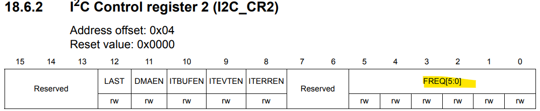
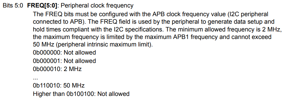
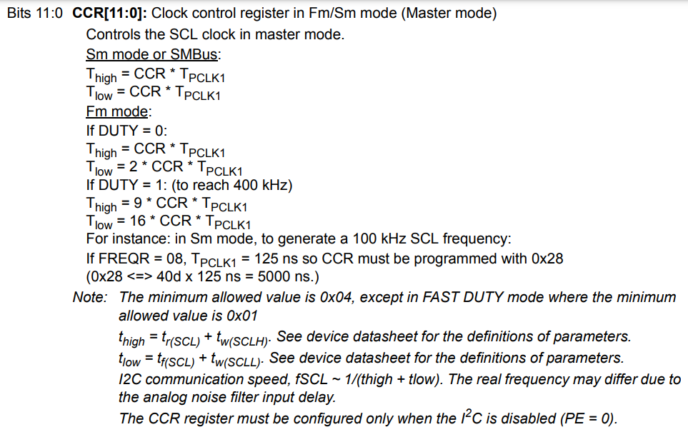
The serial clock is configured by following those registers. We need to configure the bit 15 of CCR register (SM or FM).Then, in the FREQ fields of CR2 register, we need to configure with the frequency of APB1. In our case, 16 MHz.
Then, we need to calculate and program the CCR value in the CCR fields of CCR register. 10 uS = 100 kHz. Considering 50% duty cicle (Thigh = Tlow), and TPCLK1 = 62.5 x10^-9 we have a value (for CCR) of 80 (or 0x50). In fast mode, the duty cycle MUST be configured. There are 2 options, being with Tlow = 2Thigh OR Tlow - 1.8Thigh.

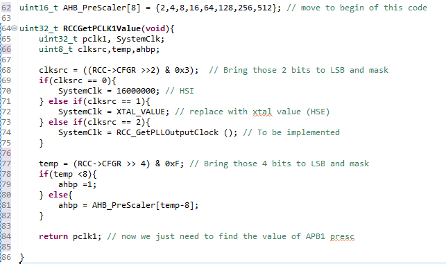
By creating a API to help us calculate the value, we need to check the RCC register.
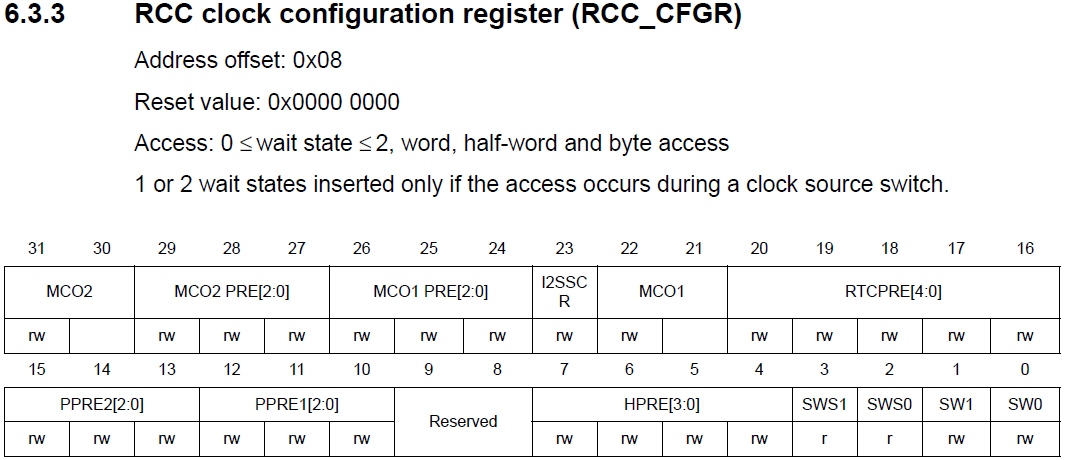
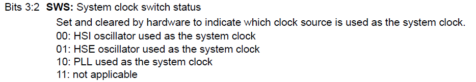
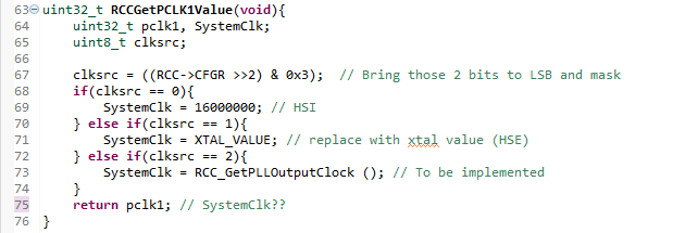
To help during the calcs of for the SCL register's value, we created a function that will read the source of clock configured (RCCGetPCLK1Value) (RCC->SWS), and another one that will calculate the PLL value if the same is being used (RCC_GetPLLOutputClock). This last one need to be implemented.
We also need to check if there is a AHB prescaler configured. for that, we need to check the bits 7:4, the HPRE (AHB prescaler):
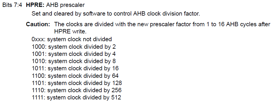
Values less than 8 doesn't change the clock source. We create an array that holds the values for the AHB Prescaler and make that the variable ´ahbp´ have its value minus 8 (to compensate the first 8 values that makes ahbp equal to 1).
Now we are going to check the bit fields for APB prescaler:
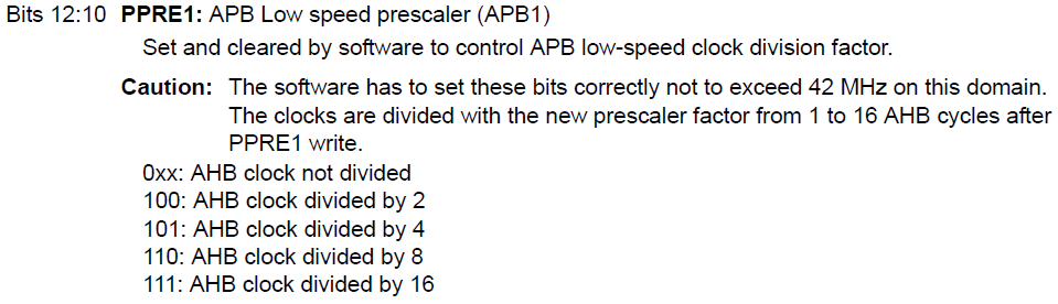
Values less than 4 doesn't change the clock source. The same for AHB prescaler was made.

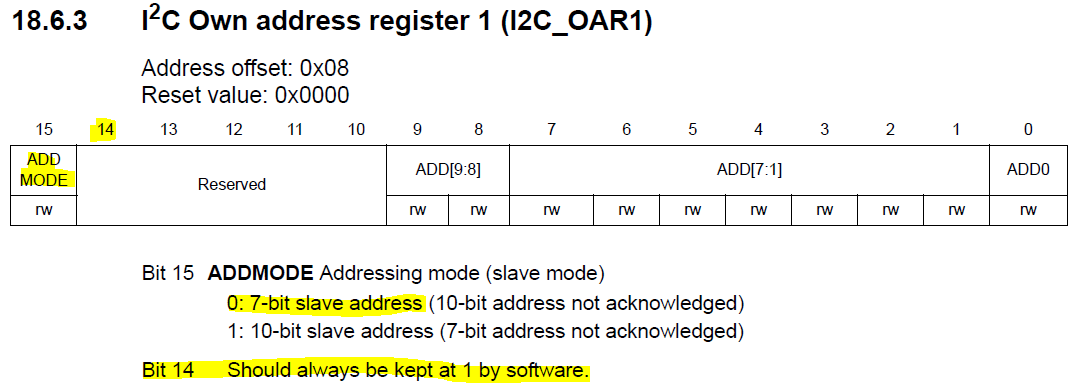
SLAVE ADDRESS
When using 10-bit slave addres, the bit fields ADD0, ADD[7:1] and ADD[9:8] are used. When in 7-bit slave address mode, only the bit field ADD[7:1] is used.

In the I2C->OAR1 register -> ADDMODE bit field, has reset value of 0, being 7-bit slave mode. There is no need of configuring, unless we are working with 10-bit mode (then ADDMODE must be 1). Also, the reference manual ask that the Bit 14 should always be kept at 1 by software.

Fist we generate the START condition (pI2Cx->CR1 |= (1 << I2C_CR1_START);). Then confirm that start generation is completed by checking the SB flag in the SR1. To easy that, we create in i2c header file the section for all flags in SR1 register.
Then we need to confirm that start generation is completed by checking the SB flag in the SR1 register (until SB is cleared SCL will be stretched (pulled to LOW)). Come FLAG macros were created to help us.
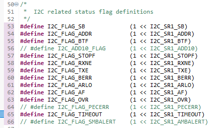
And the function to return the flag is similar to the one created for SPI.

Now we need to send the address of the slave with r/nw bit set to w(0) (total 8 bits). A private function were created for that (I2C_ExecuteAddressPhaseWrite).

Now we need to confirm that address phase is completed by checking the ADDR flag in teh SR1. This is done by sending the I2C_FLAG_ADDR parameter to I2C_GetFlagStatus function.
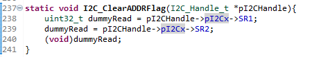
Then we need to clear the ADDR flag according to its software sequence (Note: Until ADDR is cleared SCL will be stretched (pulled to LOW)). A function was created for that.
Now we are ready to send the data. We are going to send the data until len becomes 0.
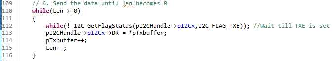
Now, when Len becomes zero we wait for TXE=1 and BTF=1 before generating the STOP condition. Note: TXE=1 , BTF=1 , means that both SR and DR are empty and next transmission should begin. When BTF=1 SCL will be stretched (pulled to LOW). We pass the FLAGs I2C_FLAG_TXE and I2C_FLAG_BTF to I2C_GetFlagStatus before gerenating STOP conditions.
- I2C pull up resistance , rise time and bus capacitance discussion
The order os the calls in I2C_Init were changed to follow the same as the teacher. The Trise were added.
void I2C_Init(I2C_Handle_t *pI2CHandle){
	uint32_t tempreg = 0 ;

	//enable the clock for the i2cx peripheral
	I2C_PeriClkCtrl(pI2CHandle->pI2Cx,ENABLE);

	//configure the FREQ field of CR2
	tempreg = 0;
	tempreg |= RCC_GetPCLK1Value() /1000000U ;
	pI2CHandle->pI2Cx->CR2 |=  (tempreg & 0x3F);

	//program the device own address
	tempreg = 0;
	tempreg |= pI2CHandle->I2C_Config.I2C_DeviceAddress << 1;
	tempreg |= ( 1 << 14); // must be kept by sw as 1
	pI2CHandle->pI2Cx->OAR1 |= tempreg;

	//CCR calculations
	uint16_t ccr_value = 0;
	tempreg = 0;
	if(pI2CHandle->I2C_Config.I2C_SCLSpeed <= I2C_SCL_SPEED_SM)	{
		//mode is standard mode
		ccr_value = (RCC_GetPCLK1Value() / ( 2 * pI2CHandle->I2C_Config.I2C_SCLSpeed ) );
		tempreg |= (ccr_value & 0xFFF);
	}else{
		//mode is fast mode
		tempreg |= ( 1 << 15);
		tempreg |= (pI2CHandle->I2C_Config.I2C_FMDutyCycle << 14); // must be kept by sw as 1
		if(pI2CHandle->I2C_Config.I2C_FMDutyCycle == I2C_FM_DUTY_2)
		{
			ccr_value = (RCC_GetPCLK1Value() / ( 3 * pI2CHandle->I2C_Config.I2C_SCLSpeed ) );
		}else{
			ccr_value = (RCC_GetPCLK1Value() / ( 25 * pI2CHandle->I2C_Config.I2C_SCLSpeed ) );
		}
	tempreg |= (ccr_value & 0xFFF);
	}
	pI2CHandle->pI2Cx->CCR |= tempreg;

	//TRISE Configuration
	if(pI2CHandle->I2C_Config.I2C_SCLSpeed <= I2C_SCL_SPEED_SM){
		//mode is standard mode
		tempreg = (RCC_GetPCLK1Value() /1000000U) + 1 ;
	}else{
		//mode is fast mode
		tempreg = ( (RCC_GetPCLK1Value() * 300) / 1000000000U ) + 1;
	}
	pI2CHandle->pI2Cx->TRISE |= (tempreg & 0x3F);
}In the source code '008i2c-master-tx-testing.c' the plan was just to spit the I2C slave address and clock. No need of a slave's acknolege. Later I plan to comunicate with another board (not an arduino).
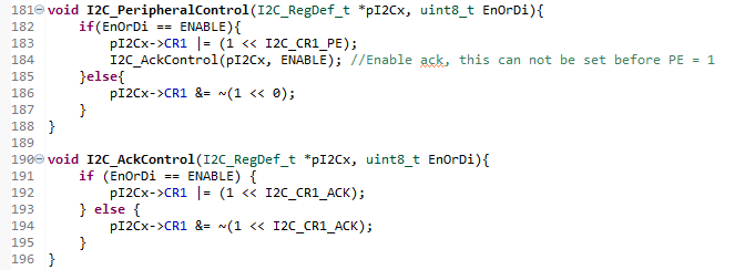
During debug I notice that the enable ack wasn't change in the CR1 bit. Browsing the Udemy FAQ, I saw that others have same issue. Another user, posted his driver's codes here in git hub, so I could see the answer. I didn't check datasheet or reference manual, but I tested and it worked. For the solution Oguz-Can. Basically, we set the ACK bit of CR1 after setting the enable bit at same register.
I also notice that MSL bit (master 1 or slave 0) could't be set. But since data and clock leaved the pins I didn't bother. But it need to be checked.

void I2C_MasterReceiveData(I2C_Handle_t *pI2CHandle, uint8_t *pRxBuffer, uint8_t Len, uint8_t SlaveAddr){
	// 1. Generate the Start Condition
	I2C_GenerateStartCondition(pI2CHandle->pI2Cx);

	// 2. Confirm that start generation is completed by checking the SB flag in the SR1 register
	// Note: Until SB is cleared SCL will be stretched (pulled to low)
	while(!I2C_GetFlagStatus(pI2CHandle->pI2Cx,I2C_FLAG_SB));

	// 3. Send the address of the slave with r/nw bit set to R(1)
	I2C_ExecuteAddressPhaseRead(pI2CHandle->pI2Cx,SlaveAddr);

	// 4. Wait until address phase is completed by checking the ADDR flag in SR1
	while(!I2C_GetFlagStatus(pI2CHandle->pI2Cx,I2C_FLAG_ADDR));

	// 5.a Read only 1 byte
	if(Len == 1){
		// Disable Acking
		I2C_AckControl(pI2CHandle->pI2Cx, DISABLE);

		// Generate STOP condition
		I2C_GenerateStopCondition(pI2CHandle->pI2Cx);

		// Clear the ADDR flag
		while(!I2C_GetFlagStatus(pI2CHandle->pI2Cx,I2C_FLAG_ADDR));

		// Wait until RXNE becomes 1
		while(! I2C_GetFlagStatus(pI2CHandle->pI2Cx,I2C_FLAG_RXNE)); //Wait till RXNE is set

		// Read data in Rx buffer
		*pRxBuffer = pI2CHandle->pI2Cx->DR;

		return;
	}
	// 5.b Read more than 1 byte
	if(Len > 1){
		// Wait until RXNE becomes 1
		while(! I2C_GetFlagStatus(pI2CHandle->pI2Cx,I2C_FLAG_RXNE)); //Wait till RXNE is set

		// read data in Rx buffer until Len becomes 0
		for (uint32_t i = Len; i>0 ; i--){
			// Wait until RXNE becomes 1

			if (i ==2){
				// Disable Acking,
				I2C_AckControl(pI2CHandle->pI2Cx, DISABLE);

				// Generate STOP condition
				I2C_GenerateStopCondition(pI2CHandle->pI2Cx);
			}
			// Read data in Rx buffer
			*pRxBuffer = pI2CHandle->pI2Cx->DR;

			// Increemt the buffer address
			pRxBuffer++;
		}
	}
	// Re-enable ack
	if(pI2CHandle->I2C_Config.I2C_ACKControl == I2C_ACK_ENABLE){
		I2C_AckControl(pI2CHandle->pI2Cx, I2C_ACK_ENABLE);
	}
	return;
}Let's connect the I2C1 to another I2C from same microcontroller (without PUPD) and try to communicate them.