Writting first code lines using NodeMCU and MQTT (Message Queue Telemetry Transport).
Comunicação assincrona, com payload menor do que o que fizemos com servidor. This is a follow up from the content of server-html1 studies using ESP8266.
In MQTT we have:
- Broker.
- Clients (can publish and subscribe to topics).
- QoS0, QoS1 and QoS2.
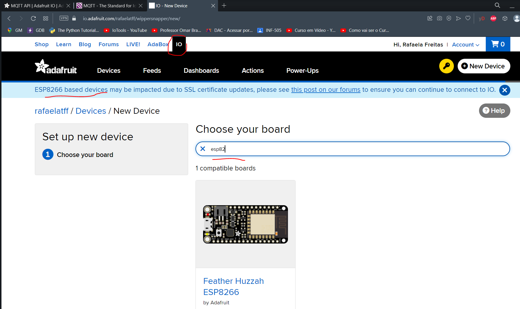
We will be using the MQTT from Adafruit, that is free at the moment of our project creation.
It looks that we will have problems, but lets go on.
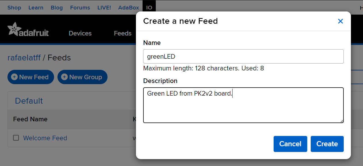
In 'Feed' we will be creating a feed for the green LED of PK2v2.
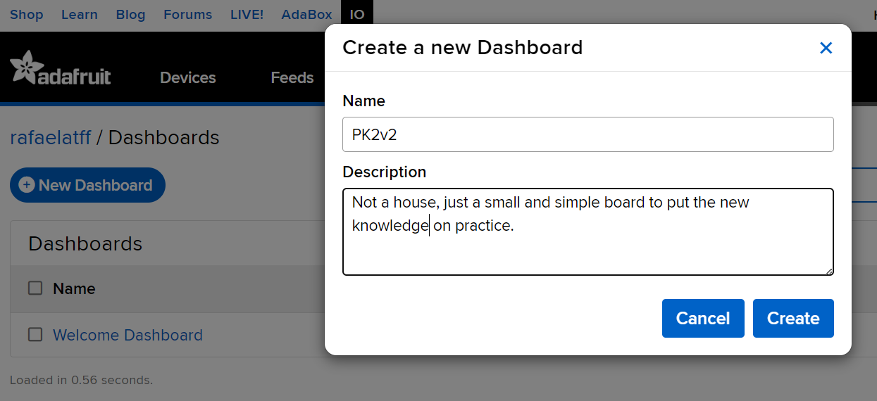
The in 'Dashboard' we will be creating our visualization dashboard, with the name of PK2v2.
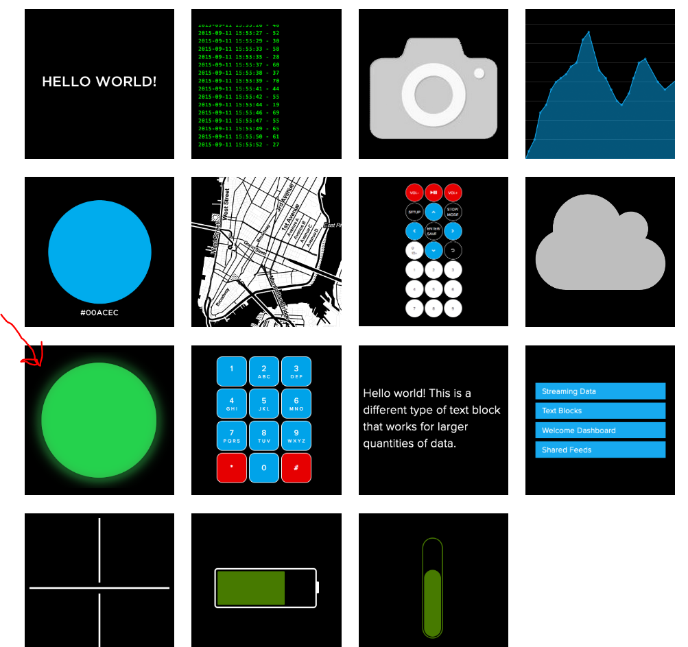
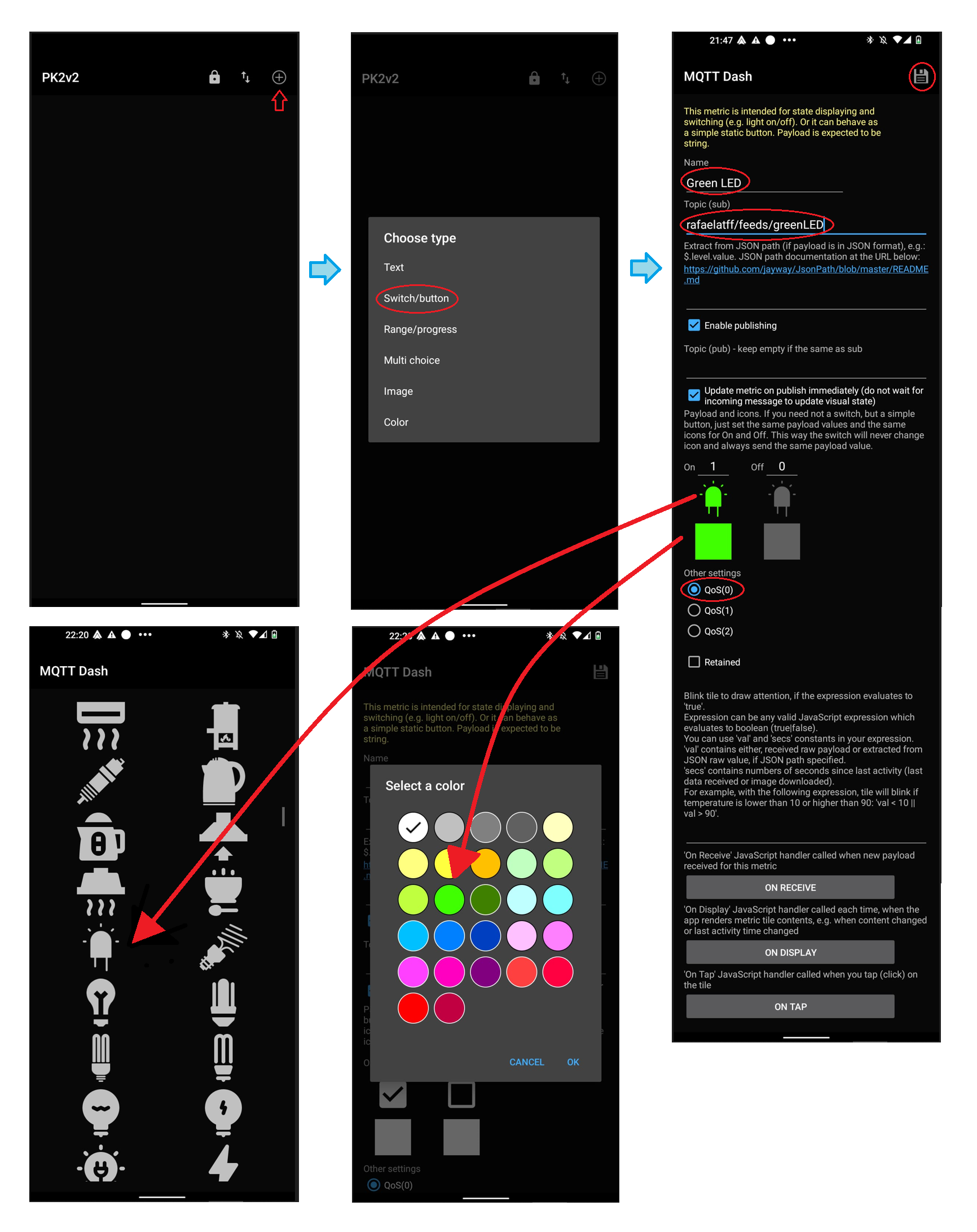
Then lets create the green LED image on dashboard:
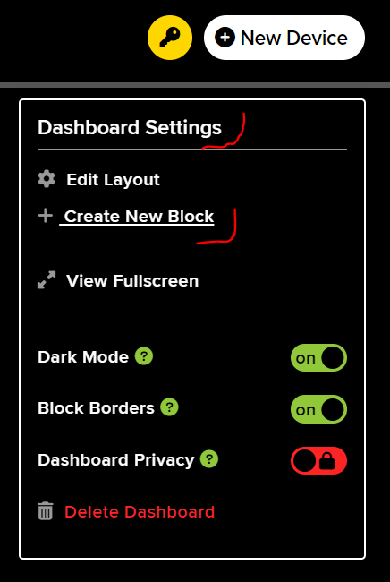
We will be using the indicator:
Connect it to the LED:
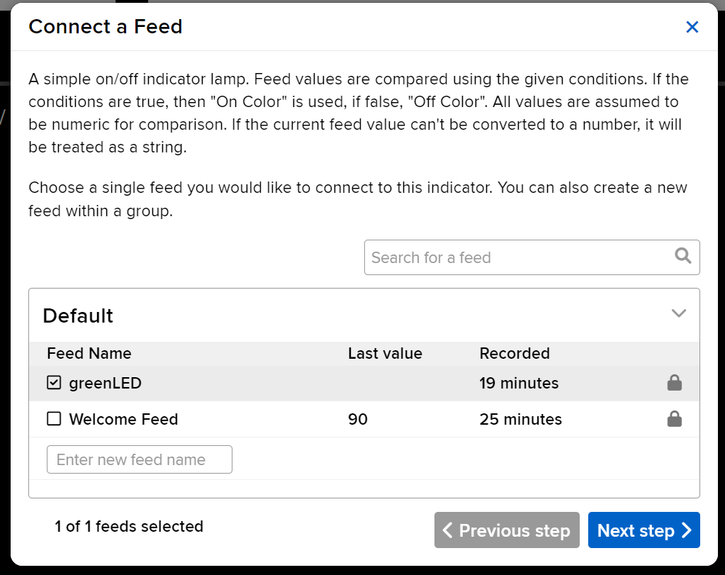
And we will add the condition for ON and OFF, and the color for both conditions:

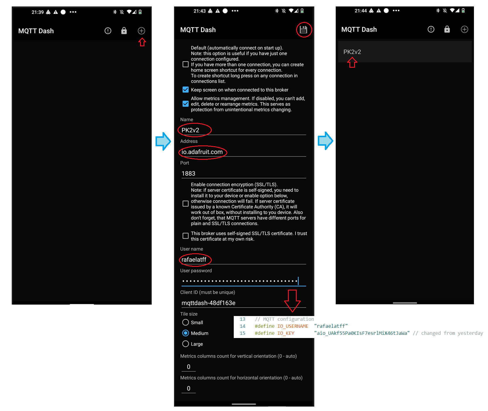
To get the credencials, just click on the key simbol and copy the Arduino lines:
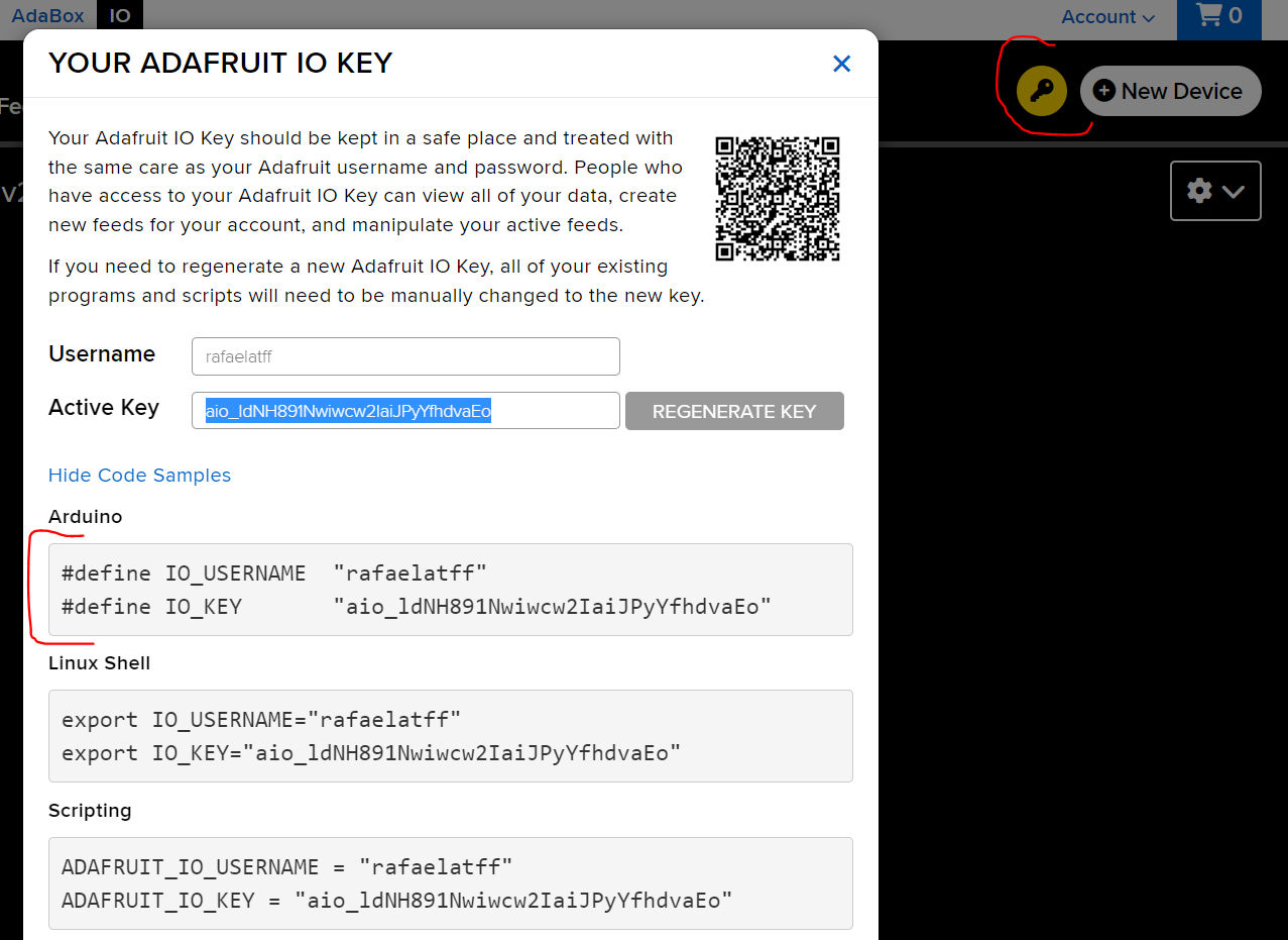
#define IO_USERNAME  "rafaelatff"
#define IO_KEY       "aio_ldNH891Nwiwcw2IaiJPyYfhdvaEo"
Then install de adafruit lib for arduino:
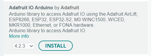
The Adafruit MQTT lib will also be installed together:
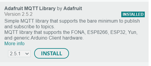
Then, we add the lib and some macros:
#include "AdafruitIO_WiFi.h"

#define WIFI_SSID "CYBERDYNE"
#define WIFI_PASS "password here"

AdafruitIO_WiFi io(IO_USERNAME, IO_KEY, WIFI_SSID, WIFI_PASS);
#define greenLED D4

// Topic configuration "rafaelatff/feeds/greenLED"
AdafruitIO_Feed *feed_greenLED = io.feed("greenLED");
In 'setup ()' we configure serial, WiFi coonection, things (greenLED) and we call:
brokerConnection();This function brokerConnection() may need connection later, that is why we kept as a function.
void brokerConnection(){
  Serial.print("Connecting to Adafruit IO");

  // Call the connection to io.adafruit.com
  io.connect();

  // call a handler to receibe the message of the greenLED
  feed_greenLED->onMessage(handle_greenLED);

  // Wait for connection to be completed
  while(io.status() < AIO_CONNECTED) {
    Serial.print(".");
    delay(500);
  }

  // Connected
  Serial.println('\r');
  Serial.println(io.statusText());

  // Update feed status
  feed_greenLED->get();
}
Then, in 'loop()'we just:
void loop() {
  // put your main code here, to run repeatedly:
  // check message
  byte state = io.run();

  // check connection
  if(state == AIO_NET_DISCONNECTED | state == AIO_DISCONNECTED){
    brokerConnection(); // if disconnected, connect again
  }
}
All this code will call a handler function, so here it is:
// Handler for the greenLED
void handle_greenLED(AdafruitIO_Data *data) {

  // Message
  Serial.print("Data  <- ");
  Serial.print(data->feedName());
  Serial.print(" : ");
  Serial.println(data->value());

  // Write greenLED output
  if(data->isTrue()) digitalWrite(greenLED, HIGH);
  else digitalWrite(greenLED, LOW);
}The serial monitor showed the following information:
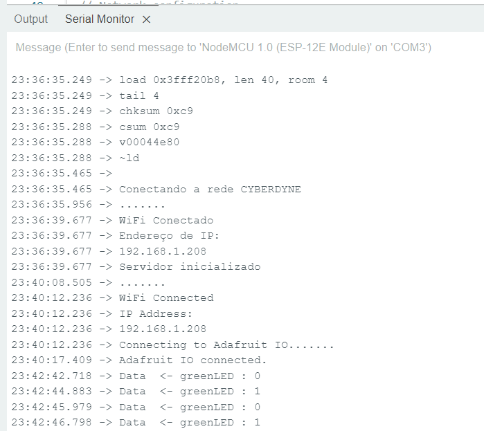
And then <3 :
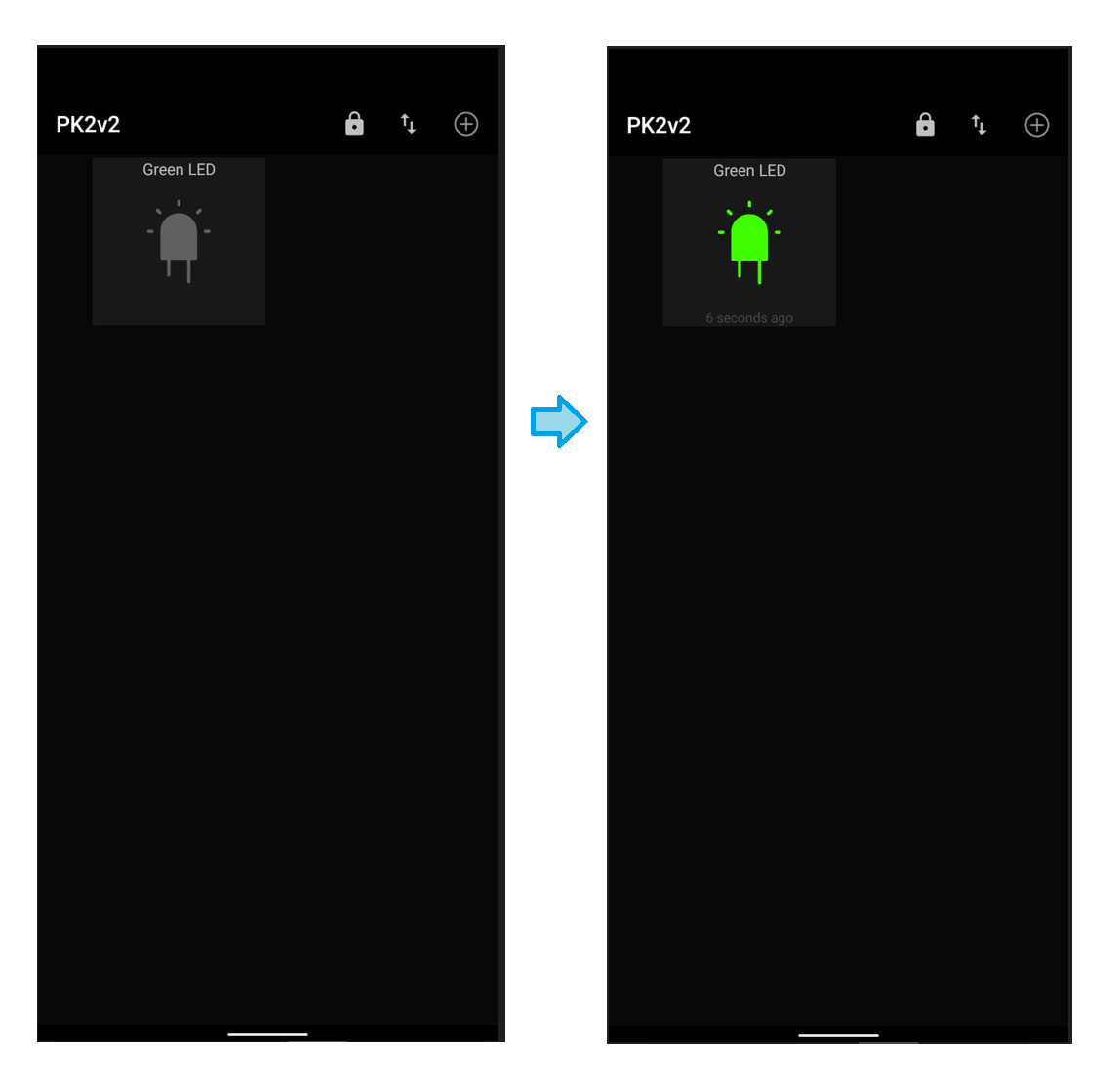
Download the MQTT Dash app on playstore. Then open the app, and make the configuration above:
Then add a new Feed (the green LED):
To check the results, I connected NodeMCU on computer, and using the io.adafruit.com website I change the status of the green LED. I was able to visualize the results on my smartphone screen, according with the status of the green LED on PK2v2 board.