Open Source Hardware Design and Software for OpenPodcar.
OpenPodcar_obstacle_avoidance_INB_Atrium.mov
I. General Info
III. Software Setup
IV. Hardware Setup
V. User Guide
VI. General Testing
VII. 3D Gazebo Simulation
VIII. Troubleshooting Guide
XI. Licence
The OpenPodcar is an affordable and open source hardware and software platform for self-driving car research. It can be used for general autonomous vehicle research as well as for human-robot interaction (HRI) studies and practical automated transportation of people and goods.
The project includes:
- Hardware design and instruction to build and wire the physical car
- Arduino software for speed control
- Pololu software for steering control
- ROS drivers for the whole vehicle steering and speed
- Gazebo 3D simulation
- move_base and gmapping integration
To build the physical OpenPodcar, first obtain the components detailed in Bill of Materials, then follow the steps of the build process detailed in Software Setup, Hardware Setup, General Testing and User Guide. The 3D simulation can be directly installed in 3D Gazebo Simulation.
Obtain the following components, which are available from many commercial suppliers and some weblinks are suggested.
- 1 Pihsiang TE-889XLSN hard-canopy scooter (branded in UK as ShopriderTraverso) e.g. Link to product
- 1 3D Velodyne Lidar (VLP-16) with its controller box e.g. Link to product
- 1 laptop under linux Ubuntu 16.04 e.g. Link to product
- 1 Laptop or computer under Windows 7+
- 1 Gimson Robotics GLA750-P 12V DC linear actuator with position feedback (250mm stroke) e.g. Link to product
- 1 ON/OF Toggle/Flick switch button e.g. Link to product
- 1 USB hub (with at least 3 USB ports) e.g. Link to product
- 1 USB A cable (Arduino <-> Laptop)
- 1 USB mini B cable (Pololu <-> Laptop)
- 1 Ethernet cable (Velodyne <-> Laptop)
- 1 Deadman push button for the vehicle ignition system e.g. Link to product
- 1 3-meter rubber cable e.g. Link to product
- 1 Joystick with its USB cable e.g. Link to product
- 1 Manfrotto Black Digi Table Tripod 709B e.g. Link to product
- 1 Inline car fuse e.g. Link to product
- 1 Fuse 7.5Amp
- 1 Relay e.g. Link to product
- A few metric HEX bolts, nuts, flat washers and cap nuts
- A few cables ties
- 2 XL4016 Step-Down Buck converters DC-DC e.g. Link to product
- 1 Arduino Uno Rev3 e.g. Link to product
- 1 Pololu JRK 21v3 Motor Controller with Feedback e.g. Link to product
- 1 MCP4725 DAC e.g. Link to product
- 1 7-segment LCD with 3 digits e.g. Link to product
- 1 Velodyne controller box (comes with the Velodyne lidar)
- 1 10K Resistor
- 1 100K Resistor
- 2 Screw Terminal Block connectors e.g. Link to product
- Male and female headers for Arduino and Pololu JRK 21v3 e.g. Link to product
- A few M1.5, M2.5 and M3 bolts and nuts
- Soldering station with solder
- Female and Male insulated electric connector crimp bullet terminals e.g. Link to product
- Female and Male insulated crimp bullet terminals e.g. Link to product
- Power supply 24V or more e.g. Link to product
- Breadboard e.g. Link to product
- Multimeter e.g. Link to product
- Gauge wires e.g. ~0.8mm, ~2mm and ~4mm diameter
- ELEGOO 120pcs Multicolored Dupont Wires 40pin Male to Female, 40pin Male to Male, 40pin Female to Female Breadboard Jumper Wires Ribbon Cables Kit Compatible with Arduino Projects Link to product
- Clamp meter e.g. Link to product
- Flathead and Phillips screwdrivers, pliers and automatic wire stripper
- Spare fuses e.g. Link to product
The OpenPodcar software stack requires a laptop working under Ubuntu 16.04 and with ROS Kinetic and Gazebo 7 installed:
- Ubuntu 16.04 installation
- ROS Kinetic + Gazebo 7 installtion
- Clone this project repository somewhere on the laptop
NB: Pololu JRK Configuration Utility tool is a Windows app, which does not work on linux.
- Install Arduino IDE on the Ubuntu laptop, instructions can be found here
- Download the MCP4725 library file and place it into Arduino's
LIBRARIESfolder - Arduino firmware source is supplied in
physicalVehicleNonRos/Arduino/ThrottleControlSerial.ino - Connect the Arduino USB cable to the laptop
- Open the
ThrottleControlSerial.inofile in Arduino IDE - Click on "Upload"
- Acceptance Testing
- click on "Tools", then "Serial Monitor"
- set baudrate to 115000
- type in some commands such as:
- "FA:170" for zeroing
- "FA:210" for forward speed
- "FA:120" for reverse speed
- the serial monitor should display the command that was typed in and the corresponding DAC value
-
Download Pololu's Windows Configuration Tool
Pololu JRK Configuration Utilityon a Windows computer by following these steps here. -
To configure the Pololu, please follow the instructions here.
-
For OpenPodCar, the steps below are followed:
-
Connect the Pololu USB cable to the Windows computer and open
Pololu Jrk Configuration Utilitytool -
Go to "Input" tab:
- set "Input mode" to "serial"
- keep all other parameters to default values
- Final settings should like in the figure below:

- Go to "Feedback" tab:
- set "Feedback mode" to "Analog voltage"
- check "Invert feedback direction"
- Under "Calibration":
- set "Absolute Max" to "2600"
- set "Maximum" to "2600"
- set "Minimum" to "1000"
- set "Absolute Min" to "1000"
- keep all other paramters to default values
- Final settings should like in the figure below:

- Go to "PID" tab:
- set "Proportional Coefficient" to "6" at the top and "1" at the bottom, so that to get a final "3"
- keep all other parameters to default values
- Final settings should like in the figure below:

- Go to "Motor" tab:
- check "Invert motor direct"
- in the "Forward column", set "Max. current (A)" to "0"
- keep all other parameters to default values
- Final settings should like in the figure below:

- Go to "Error" tab:
- you should see a window similar to the figure below with some red flags on
- set "No power", "Motor driver error", "Feedback disconnected" and "Max. current exceeded" to "Enabled and latched"
- click on "Clear" and "Reset"

- Click on "Apply settings to"
-


Here, the goal is to create persistent USB serial device names (aka Simlink) for the Arduino and the Pololu.
- In a terminal, type:
sudo nano /etc/udev/rules.d/99-tty.rules - Connect the Arduino and the pololu USB cables to the linux laptop using a USB hub, then type in the terminal:
sudo lsusb -v | grep 'idVendor\|idProduct\|iSerial'
- The above command displays the idVendor and idProduct for all the serial devices connected to your laptop and needs to be reported in the Simlink.
- Copy the following lines in
99-tty.rulesfile:
#Arduino com-port rules
SUBSYSTEM=="tty", ATTRS{idVendor}=="2341", ATTRS{idProduct}=="0043", SYMLINK+="ttyArduino", GROUP="dialout", MODE="0666"
#Pololu com-port rules -- NB the pololu has two virtual serial ports on a single USB interface.
SUBSYSTEM=="tty", ATTRS{idVendor} =="1ffb", ENV{ID_USB_INTERFACE_NUM}=="00"  SYMLINK+="ttyPololuCOM"
SUBSYSTEM=="tty", ATTRS{idVendor} =="1ffb", ENV{ID_USB_INTERFACE_NUM}=="02"  SYMLINK+="ttyPololuTTL"
- Save and close
99-tty.rulesfile - Then type in the terminal
sudo reboot - Check the status of each SimLink by typing in terminal for example:
ls -l /dev/ttyArduinoorls -l /dev/ttyPololuCOM
The lidar needs to be set up over Ethernet. The laptop must be on a wired network, not wifi. The IPs must be configured as in the velodyne, the default lidar IP is 192.168.1.201.
Follow the Velodyne installation instructions for ROS from here.
- Remove the screws from the hinges in order to remove the doors.
- Remove the seat by following the instructions given in the vehicle service manual.
Before mounting the linear actuator under the vehicle, first acceptance test it with the Pololu to check that it is functional.
This section shows how to test the linear actuactor before mounting it.
- Material: Gimson linear actuator, Pololu JRK 21v3 Configuration Tool, power supply, a breadboard, some wires (~0.8mm diameter) e.g. Dupont wires, a multimeter
- Wire the power supply "-" to Pololu's "GND"
- Wire the power supply "+" to Pololu's "VIN"
- Wire the linear actuator's "black wire" to Pololu's "A"
- Wire the linear actuator's "red wire" to Pololu's "B"
- Use the breadboard to make the following connections:
- Wire the linear actuator's "blue wire" to Pololu's "FB"
- Wire the linear actuator's "yellow wire" to Pololu's "+5V" (i.e. pin below "FB")
- Wire the linear actuator's "white wire" to Pololu's "GND" (i.e. pin below "+5V")
- Set the external power to supply 12V -> the Pololu LED should start blinking orange
- Connect the Pololu USB to a computer with the "Pololu Jrk Configuration Utility" Tool
- Open the Configuration Tool Interface and go to the "Error" tab to check that no error is displayed other than the flag "Awaiting command".
- If there are errors, click on "Reset" and "Clear" until the Poolu's LED start blinking green
- Go to "Input" tab and use the cursor or type to send commands to the linear actuator, then click on "Set Target" e.g.
- "2500" : the linear actuator should extend its length to a maximum
- "1500" : the linear actuor should reduce its length
- "1900" : the linear actuator should have a medium length. Note: this is the position that the linear actuator should have when mounting it underneath the vehicle.
To access the underside of the vehicle, this requires the help of at least three people.
-
Material: 2 axle stands, 2 jacks
-
Bring in two axle stands and set them as high as about 75cm each
-
Place the two axle stands about one meter away from the front and back wheels, both on the same side of the vehicle, as shown in red in the picture below.

-
Place two jacks right next to the front and back wheels, on the same side as the axle stands as shown in green in the above picture
-
One person should stand next to each axle stand
-
Another person should stand on the other side of the vehicle and push the vehicle from the top towards the people next to the axle stands
-
The persons next to the axle stands should adjust the positions of the stands in order to get the vehicle nicely tilted without any instability
-
The vehicle should now be tilted on one side and its underside clearly visible in order to mount the linear actuactor

- MOUNTING THE LINEAR REQUIRES DRILLING THROUGH STEEL USING A SUITABLE POWERFUL DRILL AND QUALIFIED OPERATOR.
- THERE IS POTENTIAL FOR INJURY TO UNQUALIFIED OPERATORS. THIS IS THE ONLY BUILD STEP WHICH REQUIRES A QUALIFIED OPERATOR.-
Material: Gimson linear actuator, a drill capable of drilling steel, 2 M6 HEX head bolts, 2 HEX nuts, 2 cap hex nuts and a few flat washers with 8mm diameter
-
The linear actuator must have a medium length obtained via the Pololu command "1900", cf. the Acceptance Testing detailed above.
-
There is an existing hole in the triangular part of chassis next to the right front wheel axle, shown in the figure below in the green circle. Fix the front hole of the linear actuator to this using an M6 bolt, nut, several washers and a cap nut
-
Drill a new M6 hole on the left side of the front chassis at the location shown by the red circle in the photo below.
-
Fix the back of the linear actuactor to the newly drilled hole using an M6 bolt and nuts, via washers
-
The final mounting is shown in the photo below.

-
Once the mounting is finished, bring the podcar back to its normal position (requires again at least 3 people).
-
Remove the axle stands and jacks before making the integration test of the linear actuactor.

This final test will helps to verify that the linear actuactor is well mounted and can steer the wheels as expected:
- Repeat the Acceptance Testing protocol presented above, but this time with the linear actuactor mounted under the vehicle, its wires can pass through an empty area between the vehicle plastic bumper and the left battery, and send some commands such as:
- a "2500" command should steer the front wheel to the far right, i.e about -45 deg
- a "1900" command should keep the front wheels facing forward, i.e. about 0 deg
- a "1000" command should steer the front wheels to the far left, i.e. about +45 deg
-
Material: inline car fuse, fuse 7.5Amp, ON/OFF switch, x2 12V batteries (the ones already part of the vehicle, under the seatback), some wires (use ~4mm diameter for fuse, switch and batteries, ~2mm diameter for the buck converters)
-
Switch off the vehicle batteries completely, switch is under the vehicle seatback
-
Fix a wire using a crimp bullet terminal onto each pin of the switch
-
Get access to the right battery's "+" pole and use a plier to unscrew the bolt and flat washer as shown below.

-
Strip the wire on the "+" pin of the switch by 3cm and connect it to the "+" of the right battery by tangling it around the battery "+" pole
-
Screw back the bolt and flat washer that were removed from the battery "+" pole
-
Insert the 7.5Amp fuse inside the inline car fuse
-
Connect the inline car fuse "-" wire to the switch "-" pin
-
Extend the inline fuse "+" wire by 30cm such as soldering another wire to it, then keep it safely for later connection with the buck converter "+" on the PCB board
-
Get access to the left battery's "-" pole's wire, strip a small area in the middle and plug a new and long wire (~50cm) there, then keep this new wire safely for later connection with the buck converter "-" on the PCB board as shown below.


-
Material: 3D lidar, tripod, a drill, 3 cable ties
-
Place the tripod on the vehicle's roof as shown in the photo below and use a marker to mark the positions of its three feet.

-
Remove the tripod from the roof
-
Drill two holes, ~0.6mm diameter each and their centers separated by about 1cm, on either side of each marked position as shown in the photo below.

-
Screw the lidar onto the tripod
-
Place the tripod back on the roof
-
Use the cable ties, each passed through one pair of drilled holes and around a tripod foot, to secure the tripod to the roof as shown in the photo below. (may require the intervention of two people)


Here, the buck converters' voltage and current will set to the desired values and then tested.
- Material: buck converters, power supply, multimeter, electronics flathead screwdriver, clamp meter and some wires (~2mm diameter)
- Wire the power supply "+" to the buck converter's "IN+" terminal block using a screwdriver
- Wire the power supply "-" to the buck converter's "IN-" terminal block using a screwdriver
- Insert a wire into the buck converter's "OUT+" terminal block and keep the other side of the wire safely aside
- Insert a wire into the buck converter's "OUT-" terminal block and keep the other side of the wire safely aside
- Set the power supply to 24V and turn it on
- Use the multimeter to measure the "voltage" between the buck converter's "OUT+" and "OUT-"
- Whilst reading the multimeter, use a screw driver to turn the potentiometer P1 on the buck converter until the desired output voltage of 16V is reached (or the voltage required for the linux laptop)
- Voltage Testing:
- Turn off the power supply and stop using th screw driver
- Turn on the power supply back to 24V
- Use the multimeter to check that the voltage between the buck converter's "OUT+" and "OUT-" is indeed 16V
- If not, then repeat steps 5 to 8
- Use the multimeter to measure the current between the buck converter's "OUT+" and "OUT-"
- Whilst reading the multimeter, use a screw driver to turn the potentiometer P2 on the buck converter until the desired output current of 3.75A is reached (or the maximum current required for the linux laptop)
- Current Testing
- Turn off the power supply and stop using th screw driver
- Turn on the power supply back to 24V
- Use the clamp meter to check that the current going out of the buck converter's "OUT+" wire is indeed 3.75A
- If not, then repeat steps 9 to 11
- Wire the power supply "+" to the buck converter's "IN+" terminal block using a screwdriver
- Wire the power supply "-" to the buck converter's "IN-" terminal block using a screwdriver
- Insert a wire into the buck converter's "OUT+" terminal block and keep the other side of the wire safely aside
- Insert a wire into the buck converter's "OUT-" terminal block and keep the other side of the wire safely aside
- Set the power supply to 24V and turn it on
- Use the multimeter to measure the voltage between the buck converter's "OUT+" and "OUT-"
- Whilst reading the multimeter, use a screw driver to turn the potentiometer P1 on the buck converter until the desired output voltage of 12V is reached (or the voltage required for the Pololu and 3D Lidar)
- Voltage Testing
- Turn off the power supply and stop using th screw driver
- Turn on the power supply back to 24V
- Use the multimeter to check that the voltage between the buck converter's "OUT+" and "OUT-" is indeed 12V
- If not, then repeat steps 5 to 8
- Use the multimeter to measure the current between the buck converter's "OUT+" and "OUT-"
- Whilst reading the multimeter, use a screw driver to turn the potentiometer P2 on the buck converter and set the desired output current of 3A is reached (or the maximum current required for the linear actuator and 3D Lidar)
- Current Testing
- Turn off the power supply and stop using th screw driver
- Turn on the power supply back to 24V
- Use the clamp meter to check that the current going out of the buck converter's "OUT+" is indeed 3A
- If not, then repeat steps 9 to 11
- Solder the male headers onto the DAC board pins.
- Acceptance Testing
- Material: MCP4725 DAC, Arduino, some wires (~0.8mm diameter) e.g. female to male Dupont wires, a breadboard, a multimeter
- Use a breadboard to make the following connections:
- Wire both DAC "GND" to both Arduino "GND", using two female to male wires
- Wire the DAC "VCC" to Arduino "5V", using a female to female wire
- Wire the DAC "SDA" to Arduino "SDA", using a female to male wire
- Wire the DAC "SCL" to Arduino "SCL", using a female to male wire
- Wire the DAC "OUT" to an isolated point on the breadboard, using a female to female wire
- Connect the Arduino USB cable to a computer port
- Use the multimeter to measure the voltage received on the DAC:
- Voltage between the DAC "GND" and "VCC" should give a value between "4.7V" to "5V" i.e. equivalent to Arduino input voltage
- Voltage between the DAC "GND" and "OUT" should give a value between 1.9V and 2.4V
The following items need to be 3D printed, the files are located under physicalVehicleNonRos/3D_parts:
- The LCD display support part is
LCD_support.stl - The Velodyne Lidar support part is
VLP16_support.stl - The PCB enclosure is divided into several stl files available in
PCB_enclosure/
Manufacture the PCB board by sending the gerber zip files physicalVehicleNonRos/PCB/gerber.zip to an online PCB manufacturer such as (https://www.pcbway.com). They will then post the bare board to you, usually in a few days. At this stage there are no components on it, you will solder them on later in these instructions. NB: You may wish to order several copies of the PCB in case of manufacturing errors or if you break one or more of them.
- Material: manufactured PCB board, multimeter
- Use the multimeter in continuity mode (diode symbol) to check each one of the PCB connections. If a connection on the board is continuous i.e. good, then the multimeter emits a continuous beep (takes around 5 minutes in total). If any connection is not good then the manufactured PCB board is faulty and should not be used.
- Material: manufactured PCB board, soldering station with solder, headers, Arduino, Pololu, resistors (100K and 10K), 3D printed parts for LCD display and lidar, bolts and nuts
- Solder a 10K resistor on R2 location
- Solder a 100K resistor on R1 location
- Solder male headers on the Arduino location
- Solder the two terminal blocks to their respective locations
- Solder female headers for the Pololu and the DAC
- Solder the buck converter input and output wires to the respective pins on the board
- Mount the Arduino, Pololu and DAC onto their headers on the PCB board
- Use M3 bolts and nuts to fix the lidar controller box onto the lidar 3D printed support
- Use M3 bolts and nuts to fix the buck converters, Arduino, LCD display and lidar support with controller box onto the PCB board
- USe M1.5 bolts and nuts to fix the DAC onto the board
- Use M2.5 bolts and nuts to fix the Pololu onto the board
-
Material: power supply, multimeter, some wires (~2mm diameter)
-
Connect wires between the power supply and buck converter 1's "IN+" and "IN-"
-
Measure the voltage across the PCB components, check the safety of the board and ensure that the components (especially Arduino, buck converters and DAC) work as expected, as shown in the figure below.


This step explains how to integrate a DMH and a relay in order to control the vehicle ignition system. The addition of the Relay and the DMH Switch are essential for safe operation, especially where new unproven autonomous control systems are in development. A two stage approach is used to reduce this risk. Refer to the schematic diagram DMH section in conjunction with this description.
-
Material: 1 deadman push button, 1 relay, some wires (~2mm diameter), 3-meter rubber cable, female and male insulated electric connector crimp bullet terminals, plier, flathead screwdriver
-
For the relay:
-
Connect a 2-meter wire to the relay's "-" pin
-
Connect a 2-meter wire to both the relay pins "S" and "+"
-
The relay wires should be as shown in the photo below

-
Use electrical insulating tape to wrap the relay with as shown below.

-
Use a plier to cut the two wires brown and blue connected to the vehicle ignition key
-
Attach a female insulated electric connector crimp bullet terminal to the blue wire directly connected to the ignition key for safety reasons
-
Attach a female insulated electric connector crimp bullet terminal to the brown wire directly connected to the ignition key for safety reasons
-
Connect the relay's "COM" pin to the ignition brown wire coming from the vehicle steering column using a female insulated electric connector crimp bullet terminal
-
Connect the relay's "NO" pin to the ignition blue wire coming from the vehicle steering column using a female insulated electric connector crimp bullet terminal
-
-
For the DMH:
- Connect the 3-meter rubber cable to the deadman push button
- Connect the DMH cable to the wire linking the relay "NO" pin and the ignition blue wire as shown in the photo and the circuit diagram below:


- Material: some wires (~2mm diameter), soldering station with solder, 1 plastic screw terminal block 2x2
- De-solder the middle pin of the vehicle potentiometer (white wire) and connect it to a 2-meter long wire inserted into the plastic terminal block "+" pin
- Solder a 2-meter long wire next to the potentiometer pin on the left with a yellow wire and insert in its other length into the plastic terminal block "-" pin
- Material: soldering iron, flathead screwdriver
- Solder the other side of the relay's "+" and "S" pins wire to the LCD display "VIN" pin on the PCB board
- Solder the other side of the relay's "GND" to the LCD display "GND" pin on the PCB board
- Insert the lidar controller box "+" wire to the PCB terminal block "+" pin (NB: another option would be to solder the wire)
- Insert the lidar controller box "-" wire to the PCB terminal block "-" pin (NB: another option would be to solder the wire)
- Connect the DAC "VOUT" to the plastic terminal block "+" pin linked to the vehicle speed potentiometer
- Connect the DAC "GND" to the plastic terminal block "-" pin linked to the vehicle speed potentiometer
- Connect the LCD display "SIG" wire to the plastic terminal block "+" pin linked to the vehicle speed potentiometer
- Connect the inline car fuse "+" wire (earlier set aside) to buck converter 1's "IN+" pin
- Connect the inline car fuse "-" wire (earlier set aside) to buck converter 1's "IN-" pin
- Material: flathead screwdriver, Pololu, linear actuactor, some wires (~0.8mm)
- Wire the linear actuator's black wire to Pololu's "A"
- Wire the linear actuator's red wire to Pololu's "B"
- Wire the linear actuator's blue wire to Pololu's "FB"
- Wire the linear actuator's yellow wire to Pololu's "+5V" (i.e. pin below "FB")
- Wire the linear actuator's white wire to Pololu's "GND" (i.e. pin below "+5V")
This section generally explains some steps to test the general functioning of the vehicle speed, steering, detection and tracking systems.
Implementing and testing this speed system should be undertaken with the drive wheels of the vehicle raised off of the ground, allowing for checks to be made of the DMH without the risk of the vehicle speeding off out of control.
- Material: jacks
- Place the jacks on both of the vehicle to raise its wheels off of the ground
- open a terminal and type
cd physicalVehicleNonRos/testingTools/ - while pressing on the DMH:
- type
python zeroSpeed.pyto zero the speed - type
python fastSpeed.pyto move the vehicle forward (speed commands can be modified) - type
python slowSpeed.pyto move the vehicle backward (speed commands can be modified)
- type
The Arduino serial monitor could be used to send speed commands.
The steering and Pololu can be tested with a C++ executable JrkCmd.
- Connect the Pololu USB to the vehicle laptop
- Open a terminal and make sure
physicalVehicleNonRos/testingTools/JrkCmdhas the permission to be an executable - type
./OpenPodcar/podcar/physicalVehicleNonRos/testingTools/JrkCmd Valwhere "Val" is the desired command e.g. "1900" (straight), "2100" (turning slightly on the right), "1700" (turning slightly on the left) etc.
NB:"Val" should be a value between "1000" (fully turned left) and "2500" (fully turned right).
To test the object detector and tracker:
- record a ROS bag file with some pedestrians appearing in it
- change the path of the bag file in
flobot_tracker.launchto that of the newly recorded bag file - open a terminal and type:
cd OpenPodcar/catkin_ws/src/FLOBOT
source devel/setup.bash
roslaunch flobot_tracker_bringup flobot_tracker.launch
An example video with detection and tracking results is shown below.
pedestrian_detection_tracking_demo.mov
Perform the following actions and verifications before attempting to drive the vehicle:
-
Check that the vehicle’s original lever for auto-manual is set to auto (DOWN). It is on the main motor, under the vehicle at the rear left, colored red. Requires some force to move it.
-
Power on the vehicle using the original on-off switch located under the seat on the left. It is marked ON-OFF.
-
Power on the modified electronics using the new toggle switch. (This lights LEDs on the DCDCs and Pololu, and the lidar makes a whirring sound).
-
Check that the batteries are charged (use a multimeter across one of the DCDC converters, need to see 24V or over. {\em Do not use the vehicle if it is undercharged, this is dangerous.}
-
Power on the laptop
-
Connect the lidar Ethernet cable to the laptop
-
Connect the Joystick, Pololu and Arduino USB cables to the USB hub
-
Connect the USB hub cable to the laptop USB port
-
Check that the Pololu LED flashes green
-
Check that the Arduino LED is green
-
Check that the LCD display shows a voltage between 1.9V and 2.1V
-
Press on the DMH push button and check that there is no beep
The vehicle can be remotely-controlled using a joystick as follows:
- Modify this line
<include file="/YourPath/OpenPodcar/podcar/catkin_ws/src/velodyne/velodyne_pointcloud/launch/VLP16_points.launch"/>inlaunch/podcar.launchto correspond to the global path of Velodyne point_cloud launch file in the laptop - Open a terminal and type:
cd OpenPodcar/catkin_ws/src/podcar
source devel/setup.bash
roslaunch podcar podcar.launch
If there is no error, the vehicle can then be simply controlled with the joystick as follows:
- move the Y-axis for speed control
- move X-axis for steering control
The video below shows a remote control drive of the OpenPodcar by a passenger.
OpenPodcar_remote_control.mov
This section explains how to drive the OpenPodcar in autonomous control mode using GMapping, move_base and the TEB planner.
- Change this line
<include file="/YourPath/OpenPodcar/podcar/catkin_ws/src/velodyne/velodyne_pointcloud/launch/VLP16_points.launch"/>inlaunch/podcarsim2real_laser_scan_matcher.launchto correspond to the global path of Velodyne point_cloud launch file in the laptop - open a first terminal and type:
cd OpenPodcar/catkin_ws/src/podcar
source devel/setup.bash
roslaunch podcar podcarsim2real_laser_scan_matcher.launch
- open a second terminal and type:
cd OpenPodcar/catkin_ws/src/podcar
source devel/setup.bash
roslaunch podcar podcarsim_moveBase_sim2real.launch
At this stage, two options are available to send goal commands to the vehicle:
-
Option 1: RViz GUI
- Use RViz graphical user interface to set 2D Nav goal commands to the vehicle using the green arrow.
An example of such control is shown in the following video for the vehicle parallel parking demo.
OpenPodcar_parallel_parking.mov
-
Option 2: Terminal
- open a third terminal and type:
 cd OpenPodcar/catkin_ws/src/podcar
 source devel/setup.bash
 rostopic pub /move_base_simple/goal geometry_msgs/PoseStamped "frame_id: 'map' pose: position: x: 2.0 y: 0.0 z: 0.0 orientation: x: 0.0 y: 0.0 z: 0.0 w: 1.0"
This example command will move the vehicle 2m forward in map frame whilst keeping the same default orientation.
Note: the vehicle orientation is formed by the quaternion: x, y, z and w. Euler angles can be converted to quaternions, for example using this visualisation tool
An example of the terminal based goal command is shown in the video below.
Autonomous_drive_INB_Atrium.mov
The figure below shows the complete ROS node configuration used during the autonomous driving mode.

-
Assuming: ROS Kinetic and Gazebo 7 already installed. Install instructions can be found here.
-
Rosdep is also required, but is standalone since ROS Fuerte. Install instructions can be found here.
-
To install the ros package and gazebo sim locally, clone the repository and run the follow commands (directories indicated by <> need to be replaced by their actual locations):
cd <install location>/catkin_ws
catkin_make
source devel/setup.bash
cd src/podcar/models/plugins
cmake .
make
export GAZEBO_PLUGIN_PATH=$GAZEBO_PLUGIN_PATH`pwd`:
cd ..
export GAZEBO_MODEL_PATH=$GAZEBO_MODEL_PATH`pwd`:
cd ../../../
rosdep install --from-paths src --ignore-src -r -y
roslaunch podcar podcarsim.launch
The first run of Gazebo may take a while (e.g. 5 minutes) to load because models used need to be automatically downloaded from the remote gazebo repositories.
- Once the simulation is running, you can then launch one of two different systems to control the robot: manual joystick control or movebase control.
If you have a USB joystick connected, open a new terminal and run,
source <install location>/catkin_ws/devel/setup.bash
roslaunch podcar joystick.launch
The figure below shows the complete ROS node configuration used during simulation, under manual joystick control.

Open a new terminal and run,
source <install location>/catkin_ws/devel/setup.bash
roslaunch podcar podcarsim_moveBase.launch
This will present a standard movebase GUI interface in rviz, enabling you to click desired destinations to command the vehicle to drive to.
3D simulation environments of the University of Leeds and Lincoln campuses were created in addition to the default Gazebo environment.
The University of Lincoln campus simulation is shown in the video below.
INBLincoln_3DMap.mov
-
Vehicle beeps continuous when press DMH and rear wheels do not move
-
This is due to a safety mode preventing ignition.
-
Check: is the manual-auto switch under the rear motor on auto?
-
Check: are the batteries well charged (must be 24V or over.) ?
-
Check: is the control voltage is the dead zone ? It should be.
-
-
Rear wheels do not move, control voltages are correct
-
Control voltages means the display on the voltmeter LED. Should be above 1.2 or below 2.2 for forward and backwards.
-
Check: main vehicle battery level, by connecting the vehicle charger and inspecting the battery charge level. Problem occurs if the battery is nearly flat.
-
Check: charger must be disconnected for rear wheels to move (safety feature).
-
-
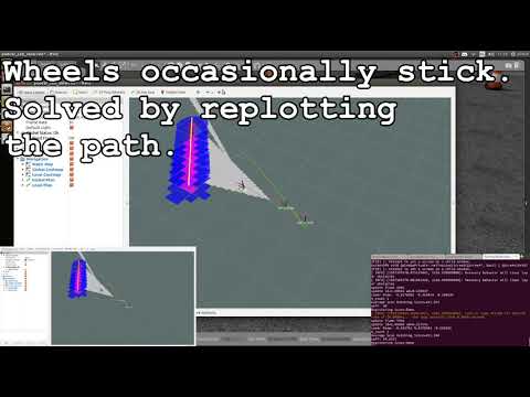
Linear Actuator
- Diagnostic test commands can be passed to the Polulo using the commands provided in /testingTools/cmdSteer. {\em Do not give commands outside the range 1000-2500 as they have mechanically destroyed the the vehicle.} A non-ROS test of the C API for the Pololu is provided in /testingTools/pololuTestCSerial.
-
Speed
- It receives commands of the form "FA:210" as speed commands. The test scripts /testingTools/zeroSpeed.py and /testingTools/testSpeed.py can be used to send example commands for debugging.
-
Simlink
- If the Simlink does not work, display all the devices by typing in terminal
ls -l /devto see whether your device is connected well. - The idVendor and idProduct can also be displayed in the commandline for each connected USB device, such as
udevadm info -q all -a -n /dev/ACM0for the device connected at COM Port ACM0
- If the Simlink does not work, display all the devices by typing in terminal
-
ROS Software:
- It is recommended to open additional terminal(s) to check topics values and data received within ros using
rostopic echo topicName, for example:rostopic echo /velodyne_pointsdisplays the lidar data (a huge flow of numbers should appear in the terminal)rostopic echo /odometry/groundTruthdisplays the vehicle position and orientation
- Other useful commands include for example:
rosrun rqt_graph rqt_graph,rosrun tf tf_monitor,rosrun tf view_frames.
- It is recommended to open additional terminal(s) to check topics values and data received within ros using
- No velodyne_points message published
-
Check: laptop must be on wired network, not wifi.
-
Check: wired network must be configured correctly, see velodyne setup docs. Maybe be interfered if wifi has been used recently.
-
Check connections to Velodyne box including power and Ethernet.
-
-
AF_NET error
- If this is thrown by the Gazebo plugin -- it may be because Gazebo is being run standalone rather than launched as a ROS node as required.
-
Cannot locate node i.e. you should make your Python scripts as executables in order to launch them
Contributions to and forks of OpenPodcar are strongly encouraged and welcomed.
Useful contributions to improve the current design could include:
-
Replace the donor vehicle’s propriatory motor driver with the OSMC open source hardware motor driver
-
Port the ROS code to ROS2
-
Update ROS code to enable swarms of multiple podcars operating together
-
Add a 3d stereo camera to the hardware and software
-
Replace the body and wheels of the donor vehicle with an OSH alternative, keeping the sensors, mechatronics, and software the same.
-
Interface the system into Autoware
Possible forks could include:
-
Port the mechatronics and software to run on other closed source mobility scooters
-
Port the mechatronics and software to run on other classes of vehicles
We would be very interested to hear about and discuss your plans, so please get in touch if interested to contribute or fork.
Email contacts: Fanta Camara (tsfc@leeds.ac.uk / fcamara@lincoln.ac.uk) and/or Charles Fox (chfox@lincoln.ac.uk)
Please cite the following paper when you use the OpenPodcar.
Plain:
Fanta Camara, Chris Waltham, Grey Churchill, Charles Fox.
OpenPodcar: an Open Source Vehicle for Self-Driving Car Research.
(under review).
Bibtex:
@Article{camara2022openpodcar,
  Title                    = {OpenPodcar: an Open Source Vehicle for Self-Driving Car Research},
  Author                   = {Fanta Camara and Chris Waltham and Grey Churchill and Charles Fox},
  Year                     = {2022},
  Journal                  = {(under review}
  }
This work is provided under GPL licence for software source code and CERN-OHL-W licence for hardware design and build instructions.
Disclaimer: Neither the authors nor the Universities of Lincoln and Leeds are repsonsible for accidents, injuries or damage caused by this vehicle design, and by downloading, building or operating the design you agree to do so entirely at your own risk. The design is not a legal product and carries no safety certification.