Getting Started: XB200 Transverter Board
This page provides an overview of the XB-200 and provides some information on its use.
The XB-200 transverter board is a block up-down converter that expands the bladeRF’s lower frequency range, allowing the bladeRF to be used in HF/VHF applications.
The RX and TX paths each have a set of 3 filters, at the 50 MHz ‑ 54 MHz (6 meter) band, 149 MHz ‑ 159 MHz (2 meter) band, and 206 MHz ‑ 235 MHz (includes 1.25 m) bands. There are also pairs of SMA connectors that will let users plug their own band filters into the RF path.
The XB-200 mates to the top of the bladeRF as follows. (There is only one possible orientation)
- XB-200 U20 to bladeRF U74
- XB-200 J5 to bladeRF J61
- XB-200 J6 to bladeRF J60
The transverter was meant to extend the range of the bladeRF without impairing the current frequency capabilities. As such, the transverter has a bypass path as well as a mixed path. The bypass path just connects the antenna port to the IF port directly without any modification to the signal.
The mixed path first has a filterbank for selectivity filtering. This filterbank consists of 4 separate paths: 50 MHz filter, 144 MHz filter, 222 MHz filter and a custom filter. The custom filter can be put in line using the filter SMA connections on the transverter.
Each of the filters was designed to try to notch the terrestrial FM band as much as possible. To be able to receive normal FM, the simplest way is to put an SMA jumper in the custom path (i.e., between the RX/TX FILT and FILT-ANT SMA connectors).
The block converter stage uses an ADF4351 to produce a 1248 MHz high-side injection tone. The mixing frequency was chosen because of it being about 3x higher than the 300 MHz highest frequency we want to use and we can run the ADF4351 in integer-N mode, reducing spurs which may have resulted from a fractional-N mode of operation. The output of the ADF4351 is always divided by 2x, so 38.4 MHz * 32.5 = 1248 MHz.
Since high side injection is used, the LMS6002D on the bladeRF is tuning to 1248 MHz - (desired frequency). Moreover, there is a spectral inversion that is occurring due to the choice of high-side injection. The LMS6002D is programmed to swap I and Q on the data bus being presented to the FPGA to correct for the flip.
There are 10 SMA connectors on the XB-200. Below are brief descriptions of each.
RX
- RXIF (J3): RX Intermediate Frequency. Connect this to the bladeRF RX port (J53) via an SMA cable.
- RXANT (J12): RX Input. Connect an antenna here.
- RXFILT (J8): Mixer-side of the RX custom filter path. Connect this directly to RXFILT-ANT to use no filter, or connect this to one end of your custom filter, and the other end of your filter to RXFILT-ANT.
- RXFILT-ANT (J9): Antenna-side of the RX custom filter path.
- ADC (J14): This SMA exposes the direct ADC sampling path (skipping the LMS6002). This can also be accessed without the XB-200 via J61 on the bladeRF.
- TXIF (J1): TX Intermediate Frequency. Connect this to the bladeRF TX port (J54) via an SMA cable.
- TXANT (J2): TX output. Connect an antenna here. When not transmitting, it is recommended to keep a dummy load or attenuator on this port.
- TXFILT (J11): Mixer-side of the TX custom filter path. Connect this directly to TXFILT-ANT to use no filter, or connect this to one end of your custom filter, and the other end of your filter to TXFILT-ANT.
- TXFILT-ANT (J10): Antenna-side of the TX custom filter path.
- DAC (J15): This SMA exposes the DAC direct sampling path (skipping the LMS6002). This can also be accessed without the XB-200 via J60 on the bladeRF.
Note SMA cables on the top are just shorting the custom filter path SMA ports together (i.e. no filtering is being done). Depending on the application, it may be desirable to insert a filter instead. If the custom path is not used, the RXFILT/RXFILT-ANT and/or TXFILT/TXFILT-ANT may be left floating. The DAC and ADC SMA ports on the XB-200 may be left floating.
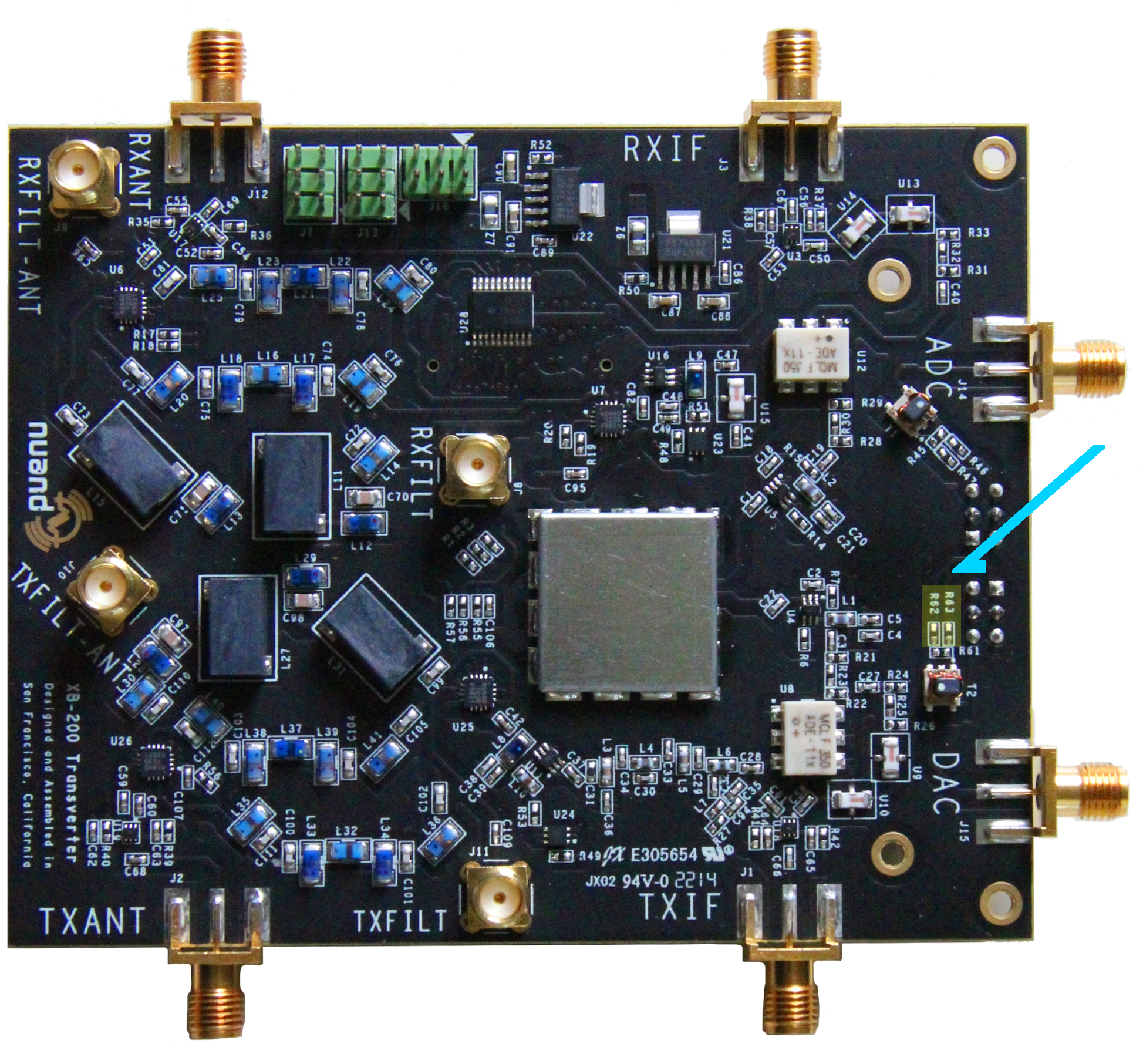
Resistors R62 and R63 on the XB-200 were populated for early production boards.
Unfortunately, this causes unbalanced loading on the analog signals feeding the RF chain and will severely degrade performance. It is highly recommended to remove R62 and R63 on the XB-200 if they are populated.
These resistors may be found slightly above the J15 DAC SMA connector, and are near the pins of J6 (image, schematic).
GPIO pins are exposed on the XB-200 via J7, J13, and J16. libbladeRF API calls to manipulate these pins are a work in progress.
From page 7 of XB200 Schematic:
| Pin | Signal | FPGA pin |
| 1 | GPIO3 | EXP_GPIO_10 |
| 2 | GPIO4 | EXP_GPIO_11 |
| 3 | VCCIO_R | 1.8 V ref (FPGA right banks) |
| 4 | VCCIO_R | 1.8 V ref (FPGA right banks) |
| 5 | GPIO1 | EXP_GPIO_8 |
| 6 | GPIO2 | EXP_GPIO_9 |
| Pin | Signal | FPGA pin |
| 1 | GPIO6 | EXP_GPIO_17 |
| 2 | GPIO8 | EXP_GPIO_18 |
| 3 | Ground | |
| 4 | Ground | |
| 5 | VCCIO_R | 1.8 V ref (FPGA right banks) |
| 6 | GPIO5 | EXP_SPI_MOSI |
| Pin | Signal | FPGA pin |
| 1 | GPIO9 | EXP_GPIO_31 |
| 2 | GPIO10 | EXP_GPIO_32 |
| 3 | GPIO11 | EXP_GPIO_19 |
| 4 | GPIO12 | EXP_GPIO_20 |
| 5 | GPIO13 | EXP_GPIO_21 |
| 6 | GPIO14 | EXP_GPIO_24 |
This section is intended to provide information regarding support for the XB-200 in various pieces of software. Please keep libbladeRF first, but feel free to add or stub out programs you'd like to see more information for.
The general procedure for using the XB-200 programmatically, via libbladeRF is as follows:
- With an open device handle, enable support for the XB-200 via:
bladerf_expansion_attach(dev, BLADERF_XB_200) - Select the desired filter bank for the RX and TX paths. For example, to configure the RX module to use the 149 MHz ‑ 159 MHz filter:
bladerf_xb200_set_filterbank(dev, BLADERF_MODULE_RX, BLADERF_XB200_144M)- See the bladerf_xb200_filter enumeration for other options.
- Specify that the XB-200 mixer path should be used:
bladerf_xb200_set_path(dev, BLADERF_MODULE_RX, BLADERF_XB200_MIX)- To tune to the "normal" bladeRF ranges, bypass the XB-200 mixer by using the BLADERF_XB200_BYPASS value with the above function.
To tell the CLI that the XB-200 has been attached, simply run the command xb 200 enable. This will expand the frequency range that the board is able to tune.
To select RX or TX filter banks, use the command xb 200 filter <rx|tx> <50|144|222|custom
auto_1db|auto_3db.
"50" refers to the 50‑54 MHz (6 meter) band, "144" refers to the 144‑148 MHz (2 meter) band, and "222" refers to the 222‑225 MHz (1.25 meter) band. Technically, the filter associated with the "222" options covers 206‑235 MHz.
The "custom" option enables the custom filter bank path.
The "auto_1db" and "auto_3b" options instruct libbladeRF to automatically select the appropriate filterbank based upon the filters' 1 dB and 3 dB points based upon the current device frequency. Outside of these regions, the custom filter path will be selected.
As of commit 9cb023, gr-osmosdr supports natively the XB-200. Note that the way to enable the board has changed slightly from the previous patched method, so be sure to read the next section very carefully and make appropriate modifications to the device string.
To enable the XB-200 in software that utilizes gr-osmosdr, add xb200 to the source/sink arguments string. By default, the filter bank selected will automatically tune with the tuned frequency at the 1 dB points. Therefore, you must have the FILT and FILT-ANT connected through a filter, or directly connected together (no filter).
If you wish to select one of the other filter paths, append one of the following to the source/sink arguments string:
xb200=50Mxb200=144Mxb200=222M-
xb200=auto- This option will select an appropriate filter path based upon the selected center frequency with 1 dB corners. This is the default if no filter is selected.
-
xb200=auto3db- This option will select an appropriate file path based upon the selected center frequency with 3 dB corners.
xb200=custom
Below is an example device string that enables the XB-200 and selects the 144 MHz ‑ 148 MHz filter:
bladerf=0,xb200=144M
As this utilizes gr-osmosdr, you can simply follow the information in the previous section regarding the device arguments.
The bladeRF can be used with SDR# via a plugin written by Jean-Michel Picod. Follow the instructions on his GitHub page, and feel free to discuss/comment/ask questions about the plugin in Jean-Michel's forum thread.
The current beta version (v2.3 build 1990 at the time of writing) of SDR-Radio assumes an XB-200 is attached, and performs the necessary calls to enable it.
If you do not have an XB-200 attached, this behavior causes a clock signal to be driven to the expansion port, which may introduce undesired artifacts. To avoid this, you can build your own modified bladeRF.dll with a change that replaces this line in bladerf.c with status = 0; to prevent the expansion board enable from taking place. You may then copy your modified DLL to the SDR-Radio installation directory, replacing the existing bladeRF.dll (which you should first back up).