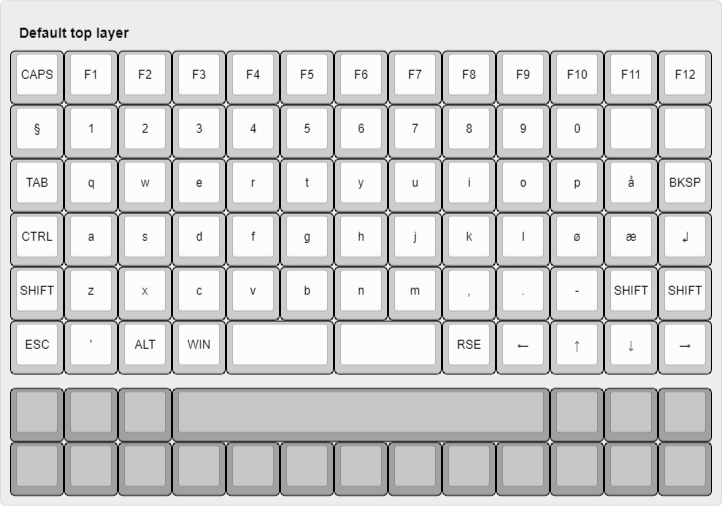
Index Tab is a 6x13 ortho keyboard. Tried to make it look like index tab that are used as dividers in drawers and
ring binders. The reason for 13 in width instead of 12 is that I’m Norwegian, and neeed that added row for æøå.
You can play around with the layout over at Keyboard Layout Editor.
It's over a year since I started on this project. I had problem soldering rev4, so decided to copy the MCU laytout from evyd13/plain60-c and pay for SMT assembly. I also had to fix the spacer holes, as they where too small for the spacers. The size was for a M2 screw. It's been changed to a 5mm hole. The OLED screen has also been removed, firstly because I choose the wrong component (so the holes where way too small), and I don't really like the look of the OLED screens.
Another big change is the change to the keyboard layout, I've removed the swiss cheeze bottom. Decided to just go for a simple 1u only row, 2x2u, or 7u bottom-row. Now you can use clip-in stabilizers. Does didn't fit the swiss cheese row.
The original plan was to be done with the project with revision 3, but looking at what I wanted to use the keyboard for, I decided to add a OLED screen to it. By doing that I could make a cool and simple keyboard switcher, with information about each switch. Will probably be a lot of work to get that to work, so we'll see if it ever will be made.
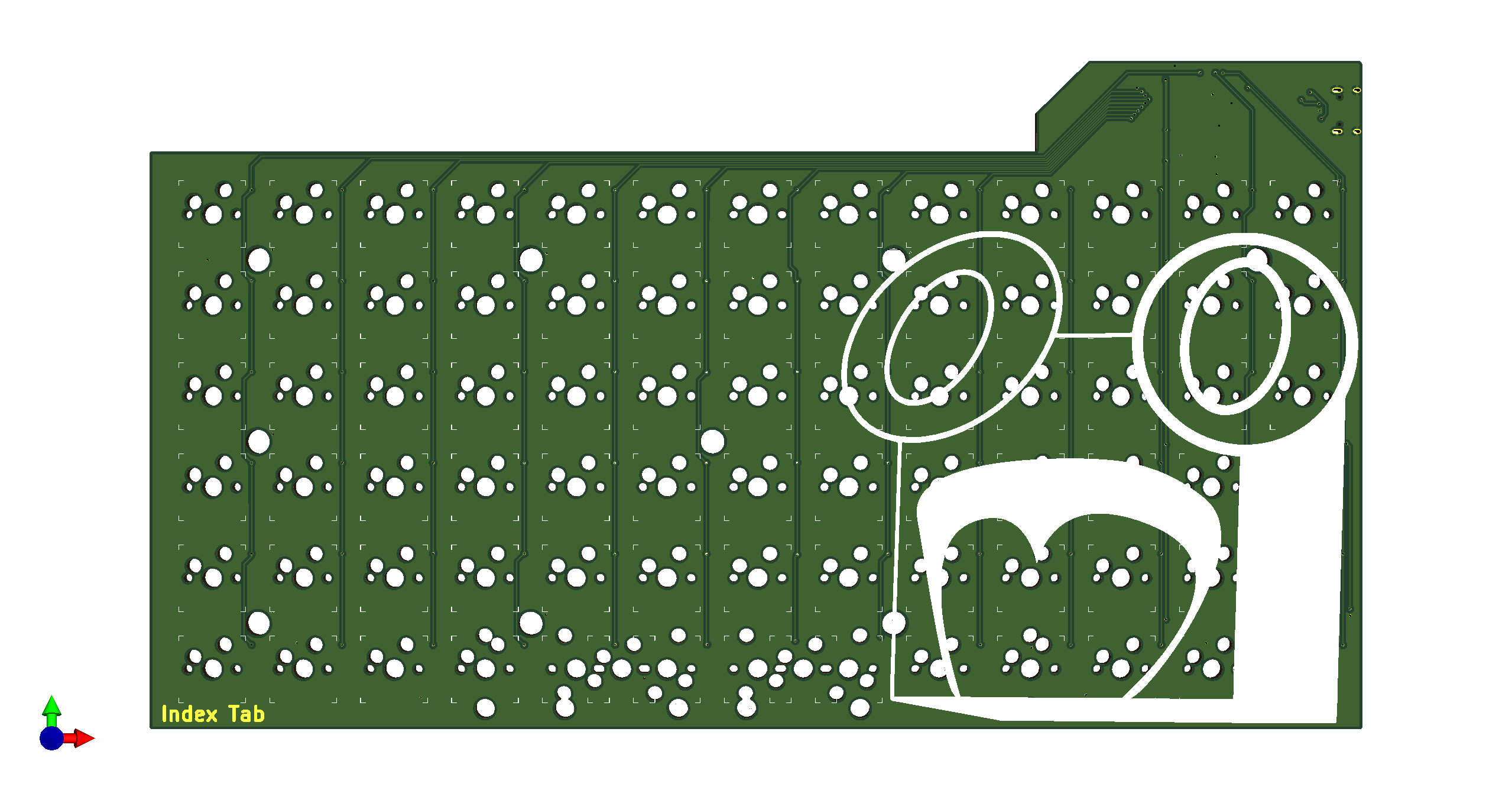
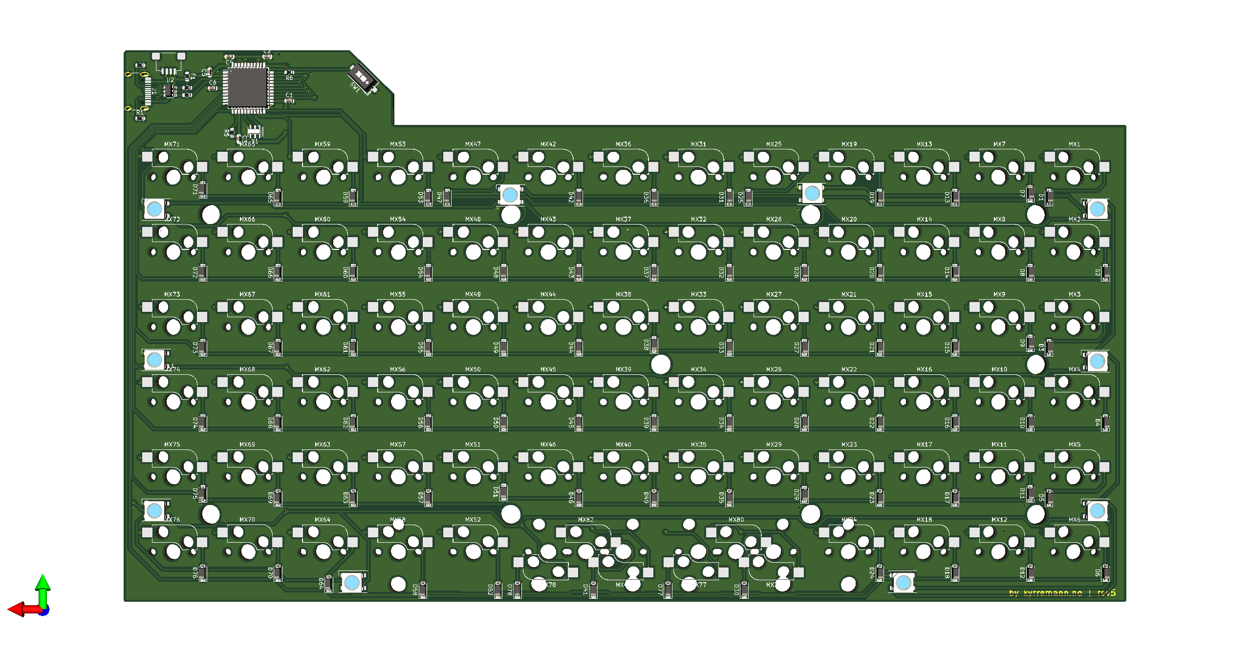
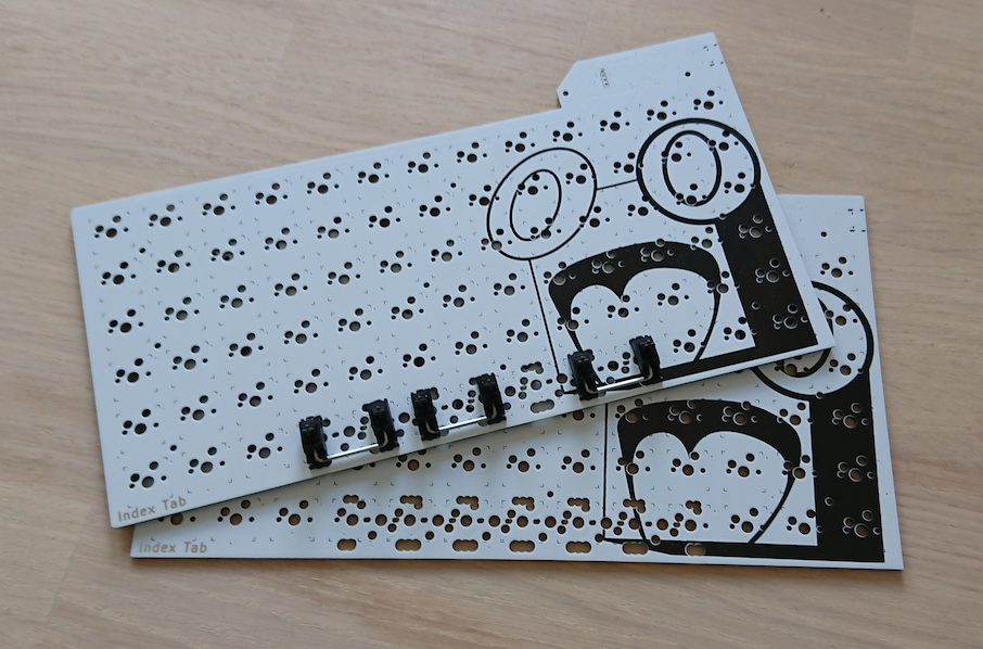
Another thing I wanted to try out, as can be seen in PCB and layout images, is the swiss cheese bottom row. It started with me adding the stabs hole that should have been in rev1, and then adding more and more, too see if it is possible! And yes, it is possible with a lot of holes, the issue I've discovedred now, is that the stabs are not fitting as good, because there are so many hole next to each other, and overlapping.
There will be one more revision before I'm saying I'm done, but that will just be to fix the small m2 screw holes for mounting, that should have been m2 spacers holes. Major mistake there...
It's going slow, like most of the world right now. I ordered the second revision before I managed to get the first one working as I was a bit afraid there where something wrong with my design, plus I was sick and tired of debugging it.
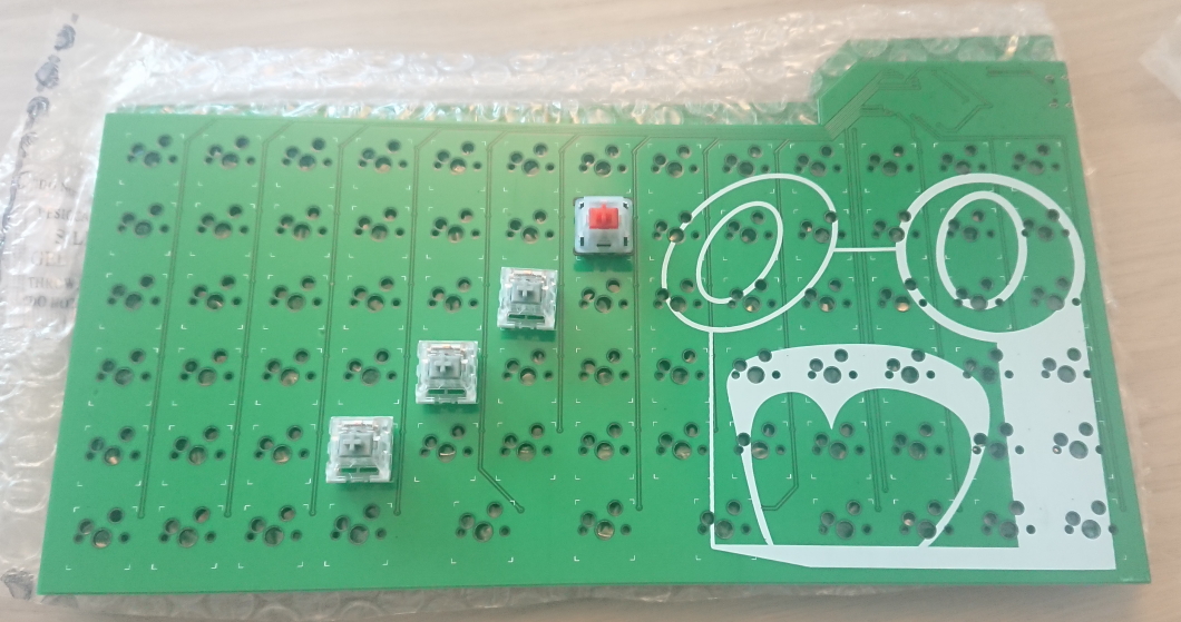
Revision 2 was ordered 30th of March, and it arrived a week after that, and it took me until now to write how it's gone. I can start of by saying it finally work! It didn't work at first, and it didn't work before I changed the capacitators for the crystal to something lower. I had originally just used the same crystal and capacitators as the UT47.2, but it turnes out to not work for the bigger ATMEGA-32U4 chip (compared to the smaller ATMEGA-32U2 chip). After good tips from both Slack and Discord, I tried a lower capacitator, going from 22pF down to 14pF, which is more correct if your using a "Load Capacitance formula", check out this Adafruit article to learn more.
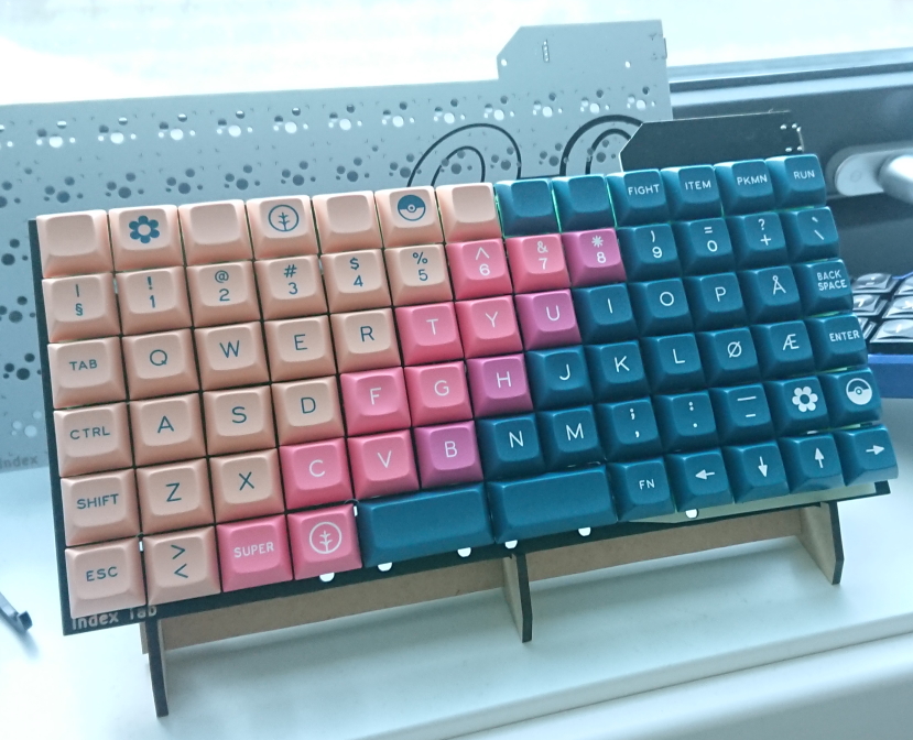
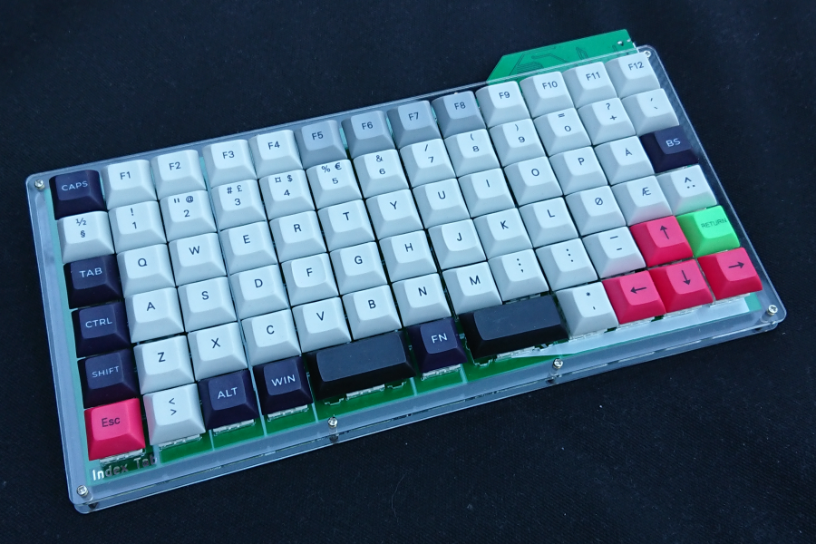
From the image below you can see that I haven't made a proper case for it yet, mostly because I'm not used to working with Inkscape, but I should be able to make a sandwich case with the tab on the top, other then that it's not much more to do for the Index Tab. I am planning a third revision, adding arrows for the diode silk print, adding holes for the stabs, and maybe making the space bar "area" more customizable.
Yesterday I received the PCB for my first keyboard. It's looks better then expected, and I'm pleased with the form factor that I choose. I also had time to solder the important bits, aka the micro controller, to see if it works.
Sadly, it looks like it doesn't. There is no connection with the Atmega-chip, and I have no idea why. There are several possibilities for this, so I need to do further debugging. One highly plausible reason is that there is bad connection with the crystal, as the footprint I choose doesn't really fit with the crystal that I ordered.
Another thing I found out is that I used a 0603 foot print for my diodes, instead of the normal SOD-123, so that is at least one thing that needs to be fixed in the next version.
I've also decided to drop the schottky-diode, as it turns out I really don't need it. I'm also thorn about keeping the power led that I've added. It's nice to see that the board is powered, but it's also pretty visible if you have RGB-leds, or just by typing. It kinda just add to the design, without being necessary.
Another foot print that I want to change is the USB-C, as I'd like to order all parts from DigiKey, instead of ordering the USB-C from LCSC and the rest from DigiKey.
Other then that there are some minor design changes I would like to do. Align all the RGBs with each other, and align all the diode at the bottom of the foot prints for the switches. Also, the holes for the switch legs where really(!) thight. That should probably need to be fixed.
That's all for now. Probably going to make a seperate blog for my keyboards, as I want to write about the Akihabare 40 and Apoptosis keyboards I ordered at the same time as my Index Tab.
For now I've got some simple renders from Kicad, enjoy!