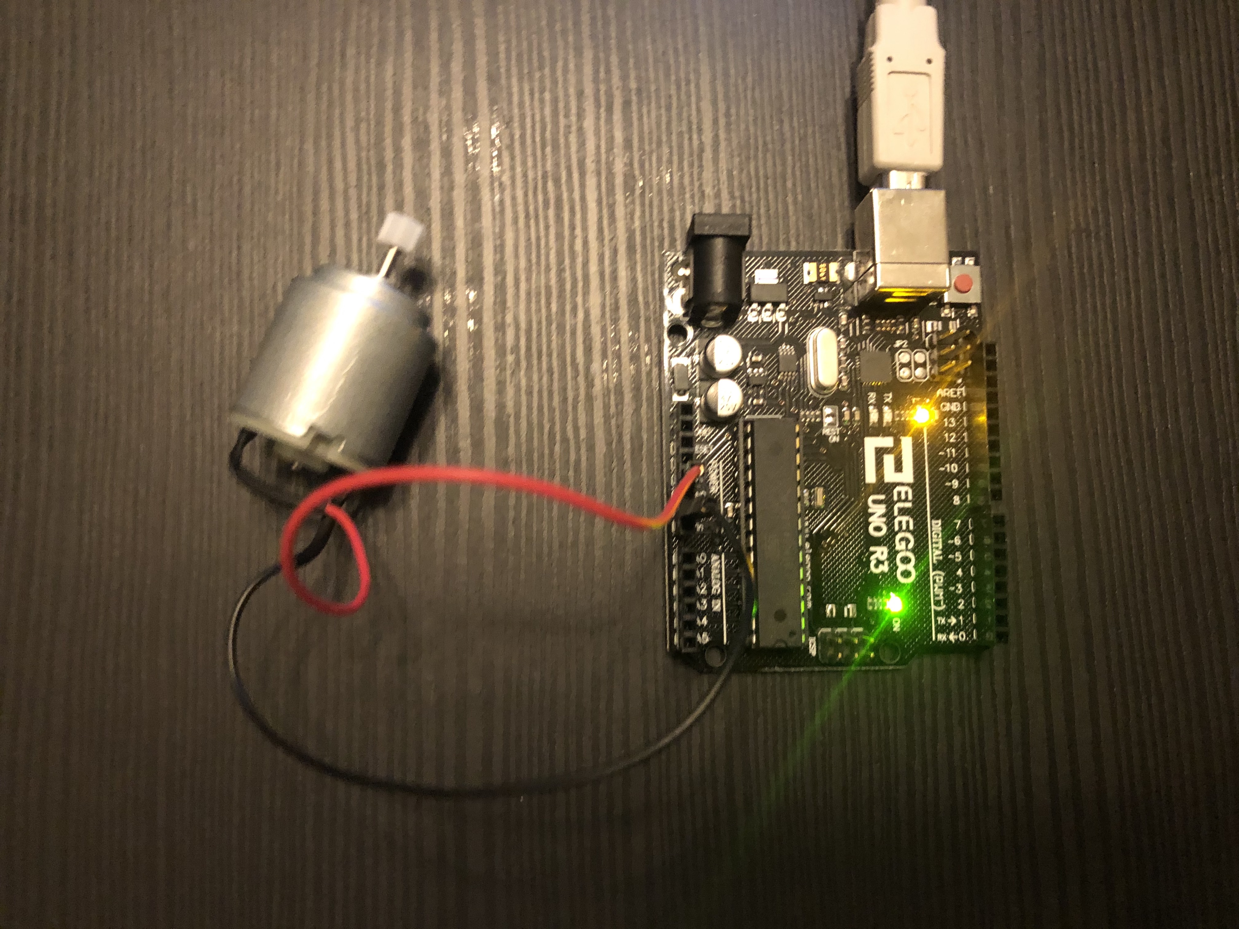
Today, I started playing with the arduino. I tried connecting it with my computer and ran some testcodes to make the arduino blink. I played with a arduino uno. I connected a DC motor to the arduino. I verified that the motor was able to run.
Today, I realized that in order to make my motor run properly, I need a motor controller.
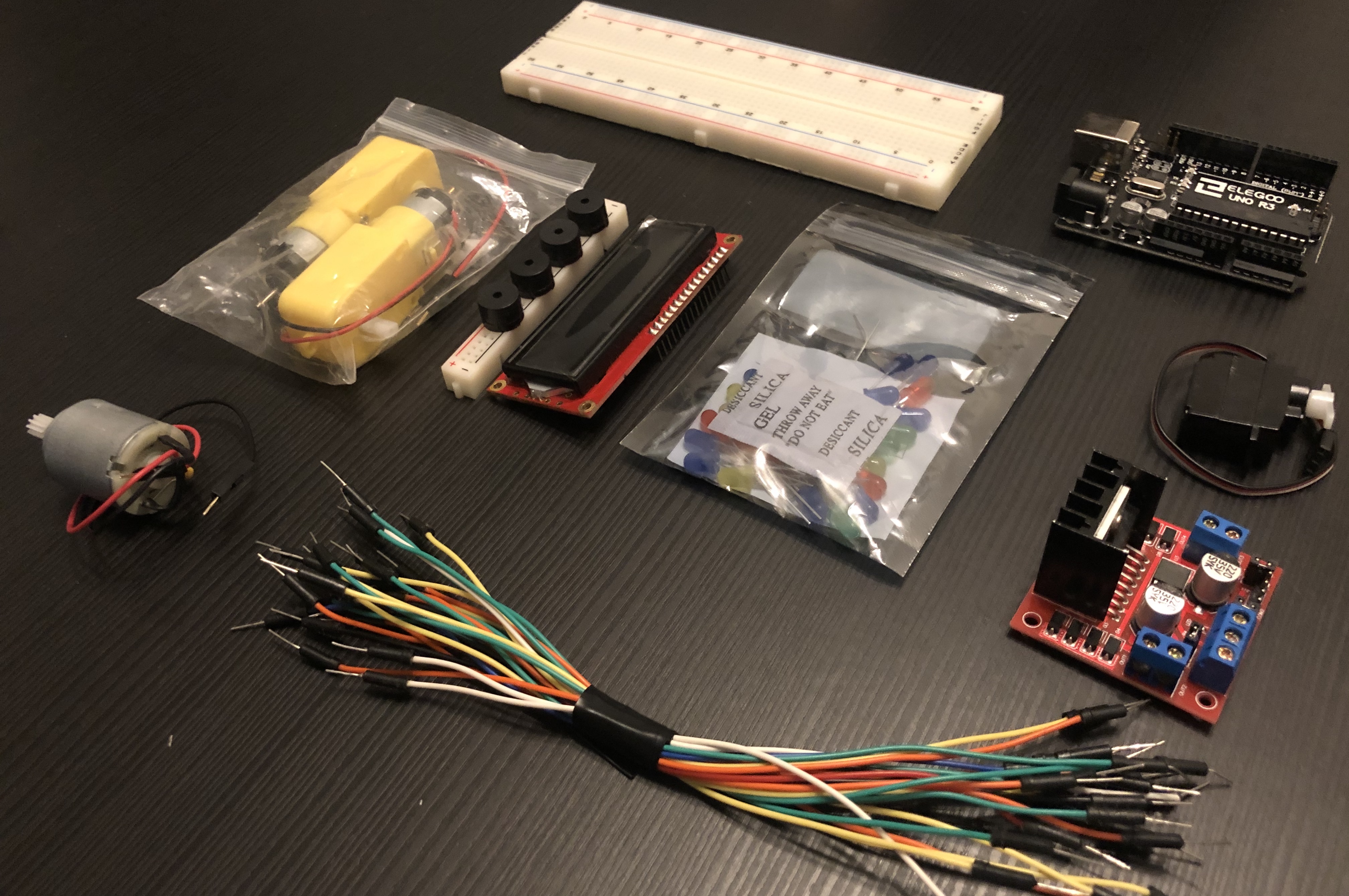
Today, my motor controller and other parts arrived. I now have LED's, LCD displays, Piezo Speakers, wires, a servo motor, and 2 geared DC motors.
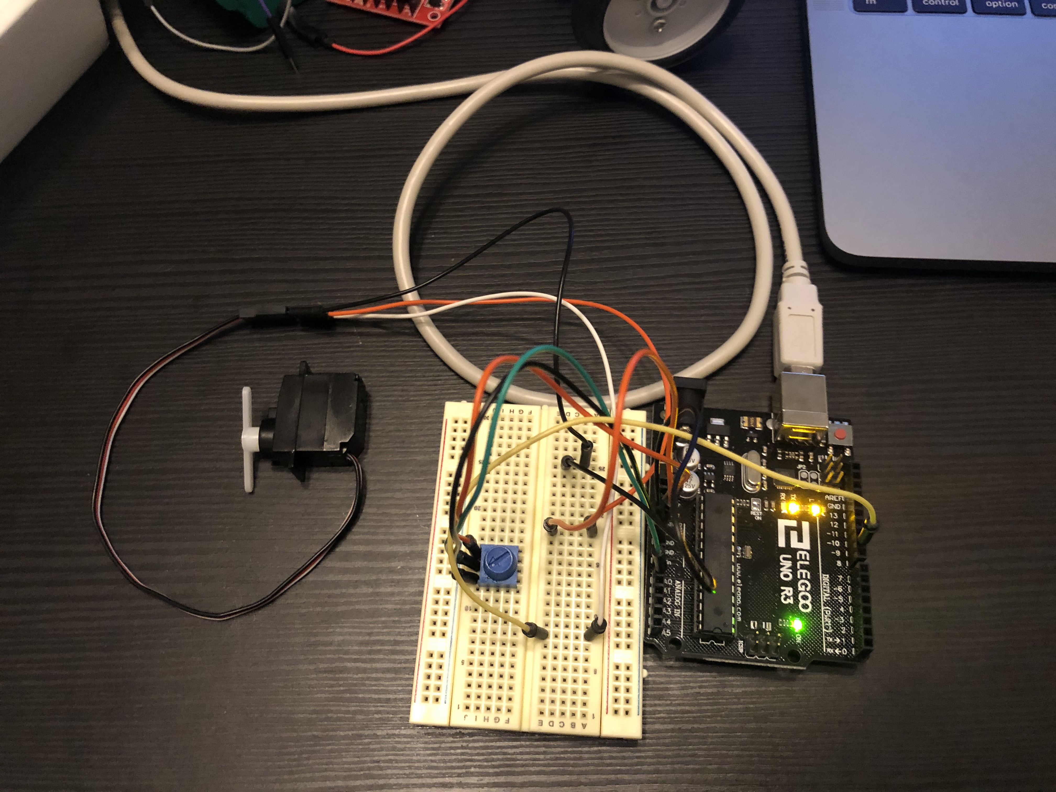
Today, I learned to connect my uno to a breadboard with a potentiometer. Using the potentiometer, I was able to control the servo and have it spin. I also learned today that based on the spin from the potentiometer, the analog number (which ranges from 0-1023) updates to the servo each time a change was made. The goal for me is to learn how to incorporate hardware with software and hopefully build a mini robot in the near future. This part is important because I need to understand how potentiometer and servo motors work and how they tie in together with a robot.
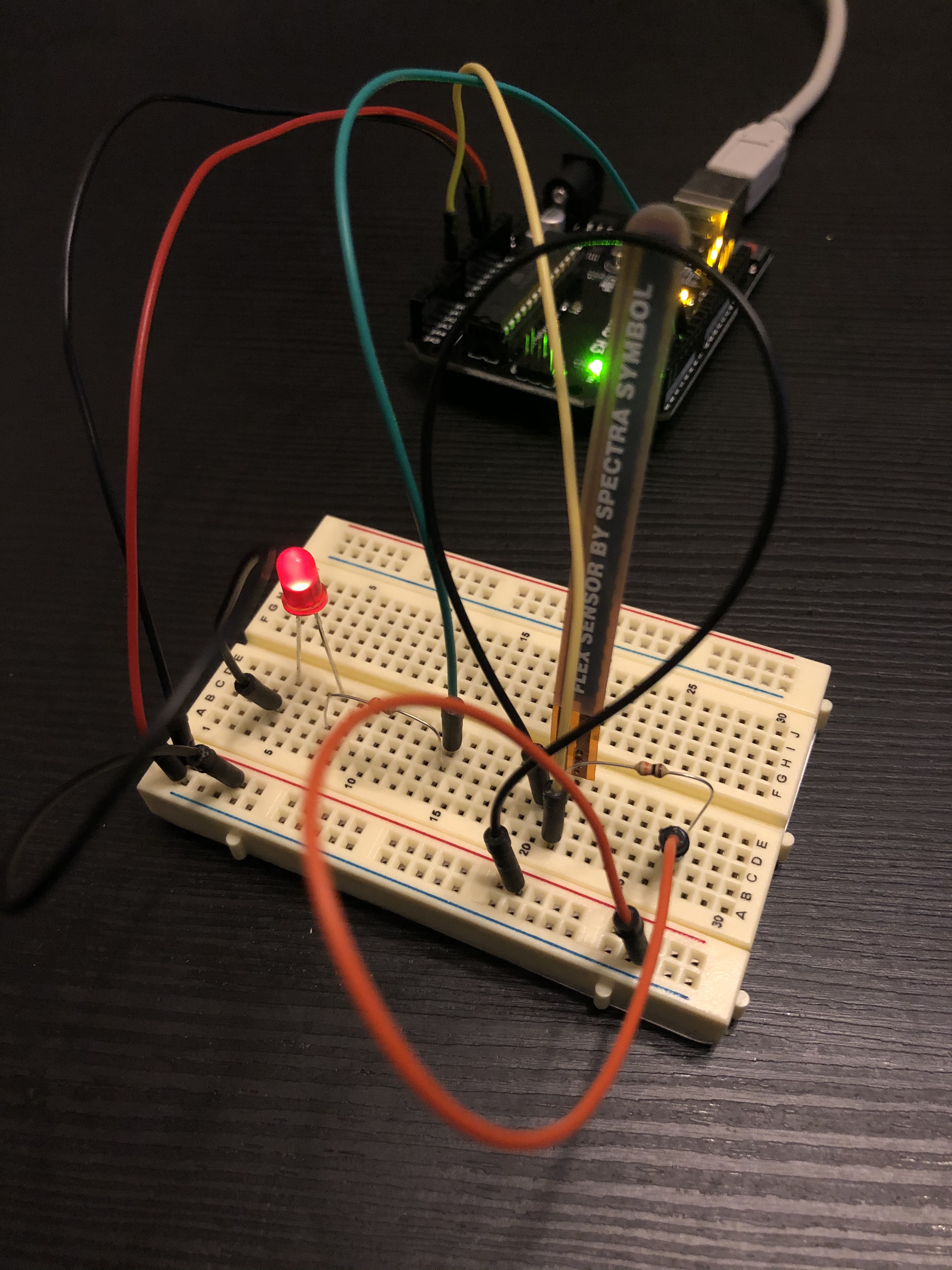
Today I was able to experiment with LED Lightbulbs with Flex sensors. I learned that Flex sensors are resistors. In this experiment, the output of the flex sensor is connected to an analog pin that send analog values to the uno board. The analog values that range from 0-1023 are then mapped to the PWM(Pulse width modulation) values that range from 0-225. After mapping out the analog values, the board then can utilize PWM waves to control the brightness that is given off by the LED light bulb. The brightness of the bulb depends on the duty cycle of PWM waves. By altering how long the power is on for and when the power is off during a cycle over many cycles, we are able to witness a change in the average voltage that a device is experiencing. For instance, a 50% duty cycle experiences a 50% power on as well as a 50% power off. As a result, the receiving device is receiving 50% less voltage on average compared to when the duty cycle sends for power to be on at all time. Knowing how PWM waves alter the voltage by deciding when to send the jolt of power, we are able to utilize the flex sensors analog values to control the brightness of the bulb.
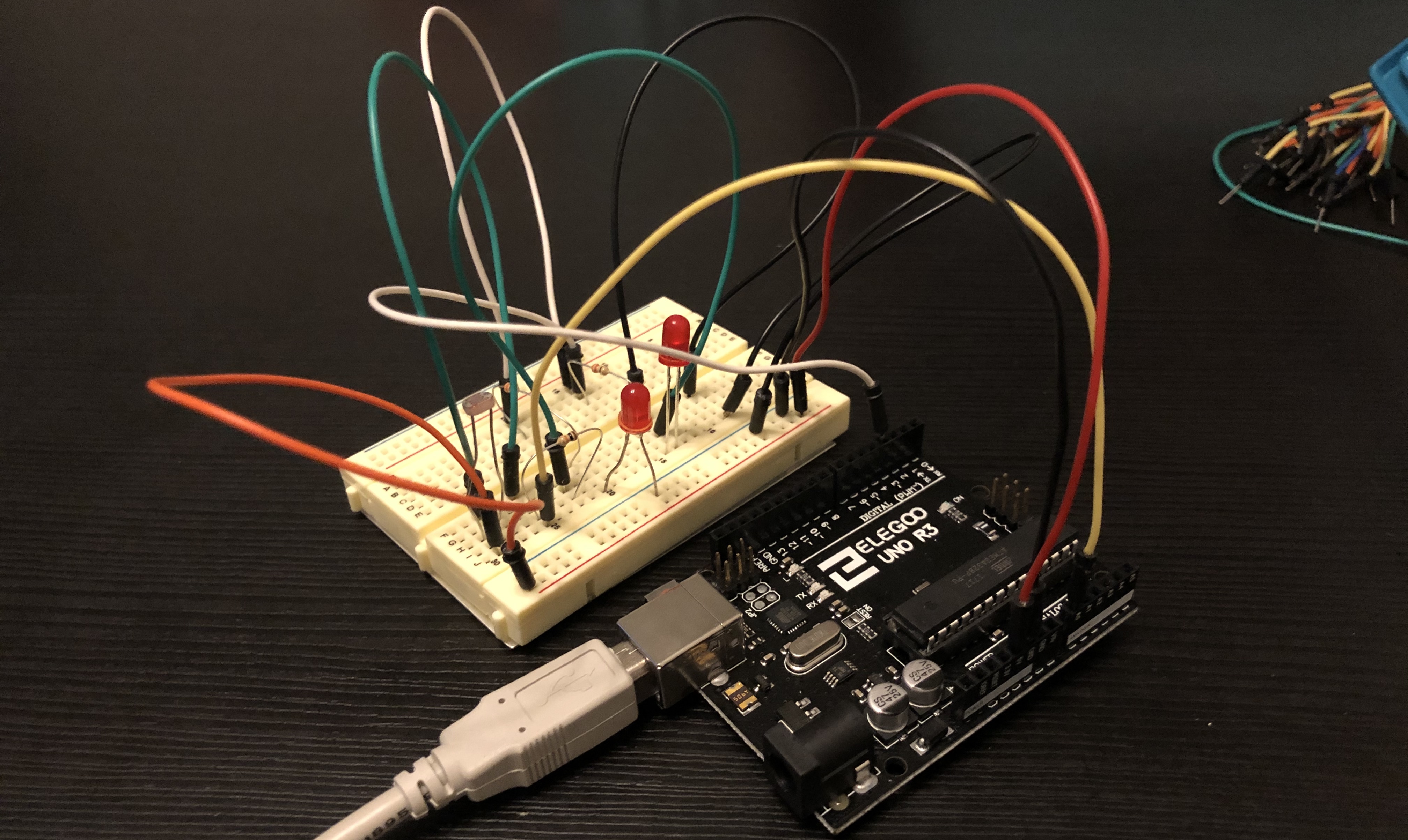
Today I experimented with a photo resistor because it came in the kit and I wanted to know its capabilities and behaviors. I wanted to know I could potentially use it on a robot in the future. Upon connecting the Arduino, photo resistor and the LED bulbs, the light would not turn on. At first, I did not understand why the bulb wasn’t turning on. However, I realized that my test code had set the sensor value to only turn on when the value is below 150. I turned on Serial.begin(9600) so I could see the analog output value coming from the photo resistor. I was able to debug that my surrounding environment gave an average value of about 300. After correcting the sensor value to turn on only when the light value is below 450, only one of the light bulbs was turning on. At first, I questioned whether the light bulb was burnt out and simply swapped it out. However, after swapping out the LED, the problem still remained. After looking through the circuit, I realized that I did not ground the LED and this was the reason why the LED wasn’t turning on. After grounding the LED, the circuit ran smoothly and I was able to test out how the LED turned on and off as a result of the photo resistor.
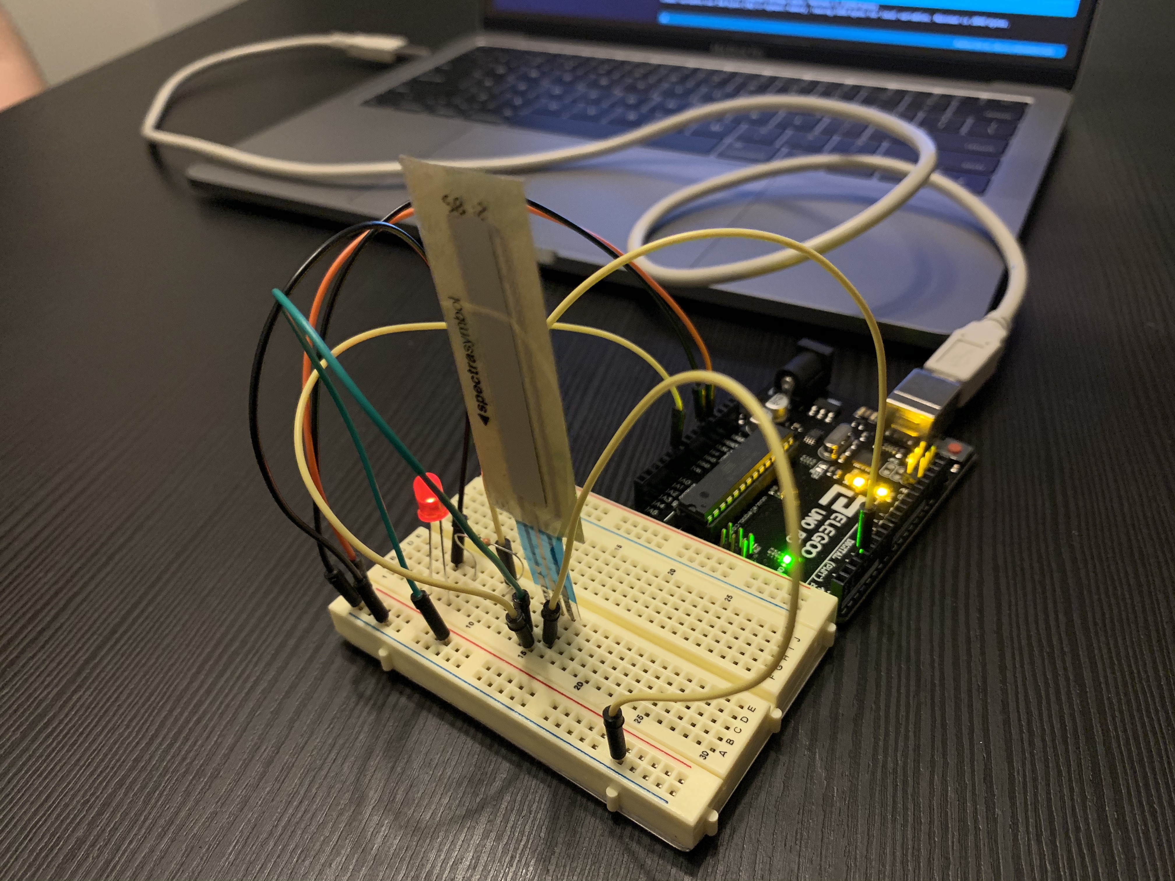
Today I was able to experiment with a Softpot Membrane Sensor. I learned that the Softpot Membrane Sensor was very similar to that of the Flex sensor. Both sensors sends analog signals as an output. While flex sensor’s value change based on the radius of the bending or flexing of the sensor, the Softpot Membrane Sensor analog values change based on the area of where the pressure was applied. By placing pressure on different points on the sensor, I was able to dim the brightness of the LED bulb or increase the brightness to a maximum as the sensor. I was able to control the brightness by mapping the analog output of the flex sensor to PWM values, and setting Pin 3 as the output to the LED. I believe that the Softpot Membrane Sensor may be useful as a mechanism of analog input. It could be very helpful in controlling the speed of the motors in my future robot.
Today I researched the importance of having sensors and the different types of sensors that can be used to aid the robot:
Sensors are important because it gives the robot the ability to determine its surrounding and analyze its environment. As a result, the robot can become an autonomous robot that is able to perform its specified action within a certain environment. In addition, there are also sensors that send electrical signals within the robot that help each individual part of the robot decide what action it needs to perform. As a result, this helps make the robot extremely flexible in the way it can adapt to its environment by changing what signals it needs to send.
An ultrasonic sensor is used to determine the distance between the current position of the robot and an object in the distance relative to itself. To determine its position, it sends out ultrasound waves through its transducer which then bounces off objects and creates an echo. This echo returns to the sensor and counts the sensor determines how long it takes to come back at the sensor. However, to use the information obtained by the sensor to calculate the distance, you will need to know D=1/2TC where C represents the speed of sound.
An infrared sensor is able to determine its environment by analyzing the infrared radiation of its surrounding. Since any light source/ heat source above 5 degrees kelvin emits infrared radiation, most of the robot surroundings can be detected by the sensor. While infrared sensors simply detect infrared radiation, there are two kinds of sensors: passive and active. For active sensors, when an objects gets close to the sensor and triggers a reaction, the LED shines infrared waves that reflect back off the object and back at the receiver. For passive sensors, they only detect the existence of infrared waves but don’t emit infrared waves from LED itself.
The LiDar sensor, also known as the light detection and ranging sensor is used to measure distances such as the surface of a planet. By illuminating the area with a lasers light, it can measure the reflection of the light and then use the different lightwaves to create a 3d representation of the surface. In order to map the environment, it has to perform calculations that determine the distance between the objects similar to that of an ultrasound sensor. By tracking how long it takes for each pulse of the sensor to return back helps derive the distance between the 2 objects.
An Arduino gyroscope is a sensor that is comprised of two main abilities. The gyroscope has the 3-Axis Accelerometer that can detect the gravitational acceleration of an object. This is possible due to the sensors ability to trace along 3 axes and calculate the angle at which the sensor is located at. The second part is the 3-Axis Gyroscope which measures the rotational velocity. It is able to calculate the angle by pulling it from the velocity determined by the sensor. Putting the Accelerometer and the Gyroscope gives information on the sensor orientation. As a result, this is extremely useful within a robot as by having a sensor determine the location, it will know what next steps it should be taking or its surrounding area.
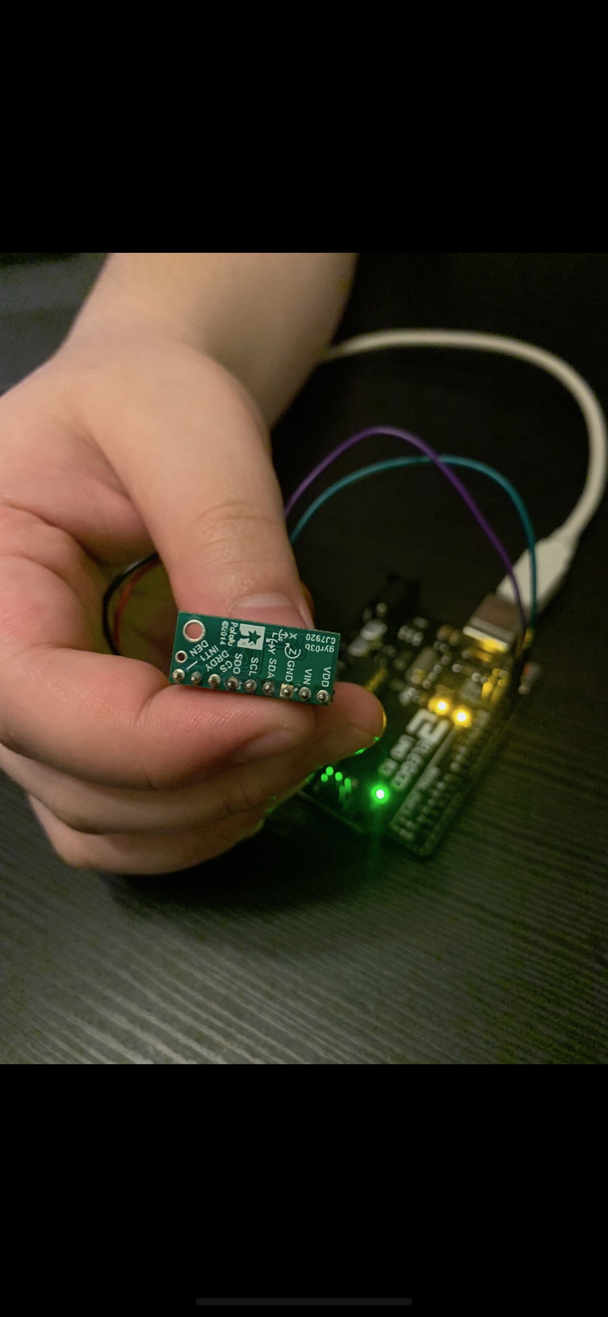
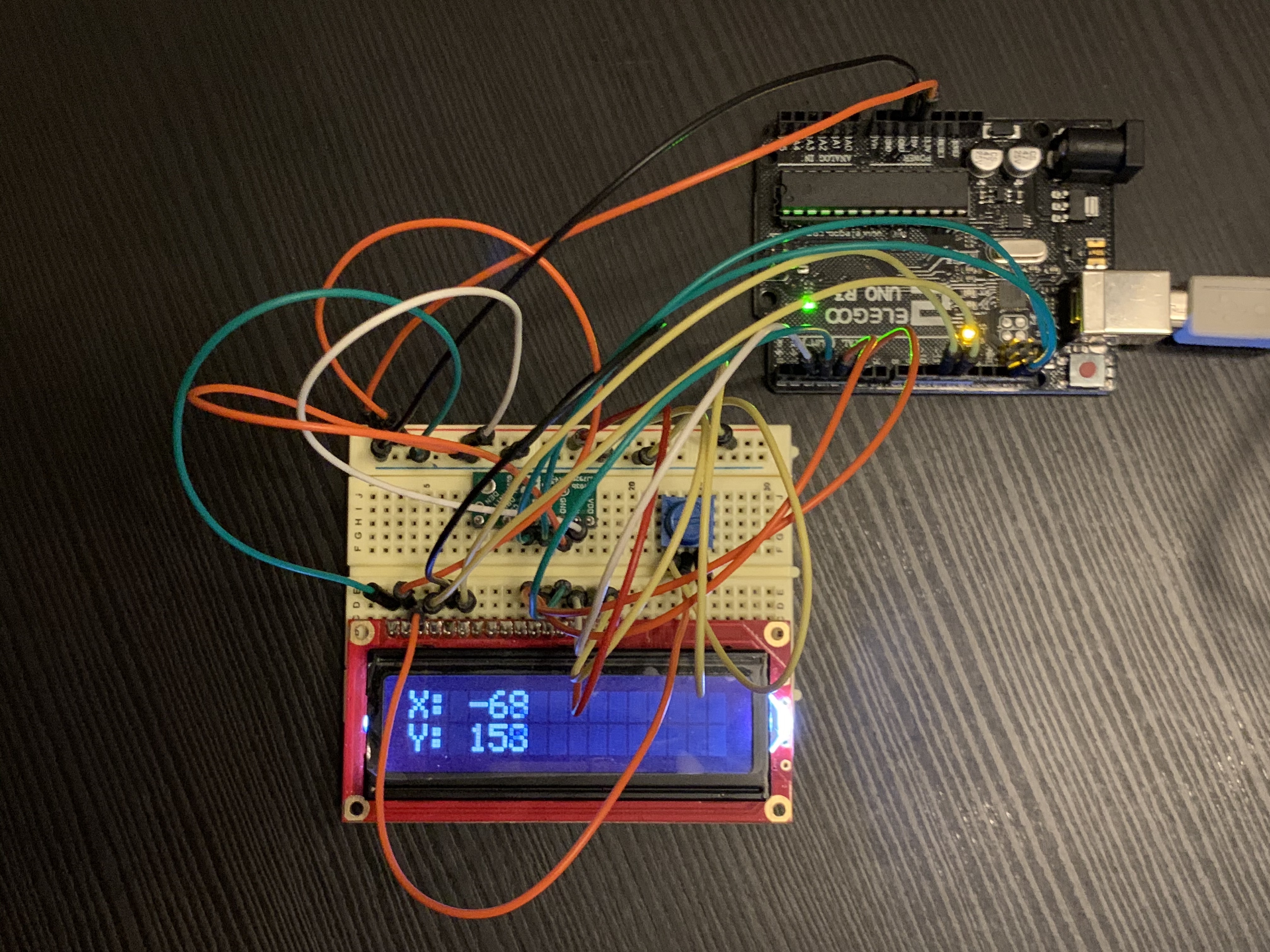
Today I worked with both the gyroscope and The LCD display. At first, I experimented with the gyroscope by checking the serial monitor. From the monitor, I saw that the sensor was inputting coordinates based on its surroundings. From the results, I initially concluded that the gyroscope sensor was extremely sensitive. After testing out the sensor, I started working on connecting the LCD display and the Arduino to display a simple message of “Hello World.” Upon completion, I was able to display any 2 line message I wanted successfully. With an understanding in how the gyroscope works and a working LCD display, I decided to try and have the LCD display the values recorded from the gyroscope. However, when I tried to have the display load the output of the gyroscope, the display did not clear the values completely each time the values were updated. By tweaking the display to have a full screen clear with a delay, I was able to record different values each time. After fixing the values not clearing, I saw that the LCD display was only able to display the X and Y coordinates from the gyroscope. This could not be resolved due to the limited space available on the small LCD display. However, there was still another problem within the experiment which stemmed from the library folder I was using. The L3GD20H library folder was taking into account the gravitational acceleration of the earth which was I initially concluded the sensor was extremely sensitive. I decided to switch to the Adafruit gyro library folder which provided us with more accurate values for the experiment. From this experiment, I was able to learn how to have data be displayed on the LCD display. The experience I received from this lab is extremely useful as when I decide to build a robot, a gyroscope sensor will come in handy when I want the robot to be able to determines its current location. Working on the LCD display was also a valuable experience as I will be able to utilize the display to notify me if an error occurs. By knowing when an error occurred within the code while not connected to the laptop will help make the building process a lot easier.
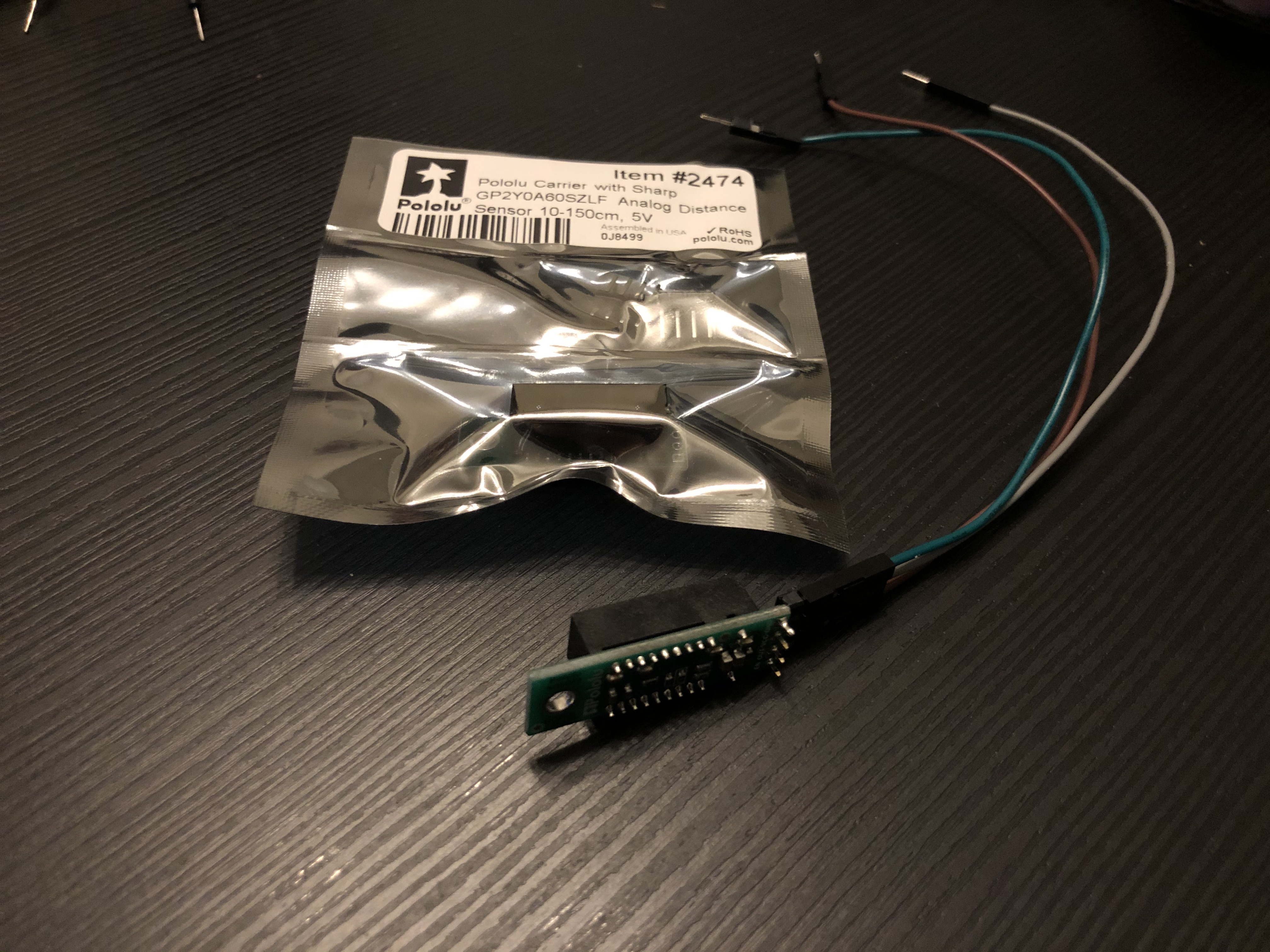
Today, I experimented with the IR sensor. While experimenting with the sensor, I was able to see the limits of the accuracy of the sensor. From what I observed, I realized that the sensor was not able to give an accurate estimate on any object that was less than 10 centimeters away from the sensor. Anything within this range will produce a faulty answer. As for the observations beyond 10 centimeters, within a 30 centimeter range, it provided pretty accurate results. However, beyond the 30 centimeter mark, it had many fluctuations in part due it trying to calculate the distance between the various objects. I also attempted to write a code that translated the values produced by the sensor to centimeters to make it easier to understand.
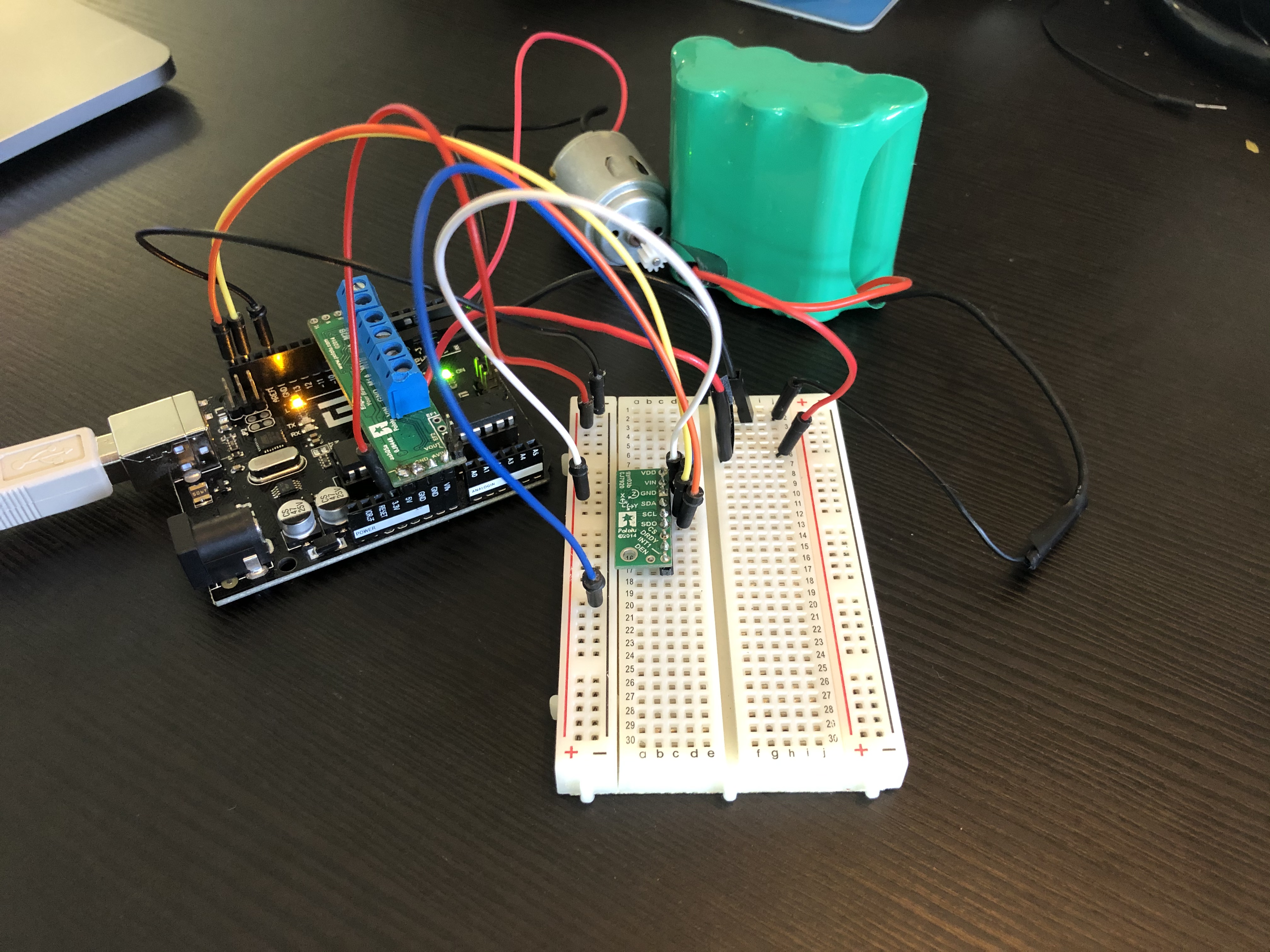
Today I attempted to connect my motor and the L298N motor driver. I found out that I could keep the jumper and set the motor speed to be high or low instead of using enable pins to control the speed of the motor. After connecting the motor and the motor driver, I decided to test out the system by connecting it to a power supply. However, when I connected the wires to the battery, the motor did not budge. I took me a bit to realize that the battery was not a 12 volt battery but rather an 8.4 v battery. This resulted in the motor driver input not receiving enough power for the motor to spin so the motor would not run. In order to correct this, I gave an attempt at the 5v input but this also gave similar results. The motor did not function as it normally would and the reason was that the input was outside the acceptable range for the motor. After going through this, we decided to try and utilize the Pololu dual motor shield as the new motor driver. With the new motor driver, we were able to effectively get the motor to start spinning. However, during the process, a problem arose as the LCD display produced random numbers and symbols and not the values from the gyroscope. After dismembering the LCD display and attempting to reconnect the wires multiples times, the LCD display produced the same results. From this result, we decided to remove the LCD display from the robot.
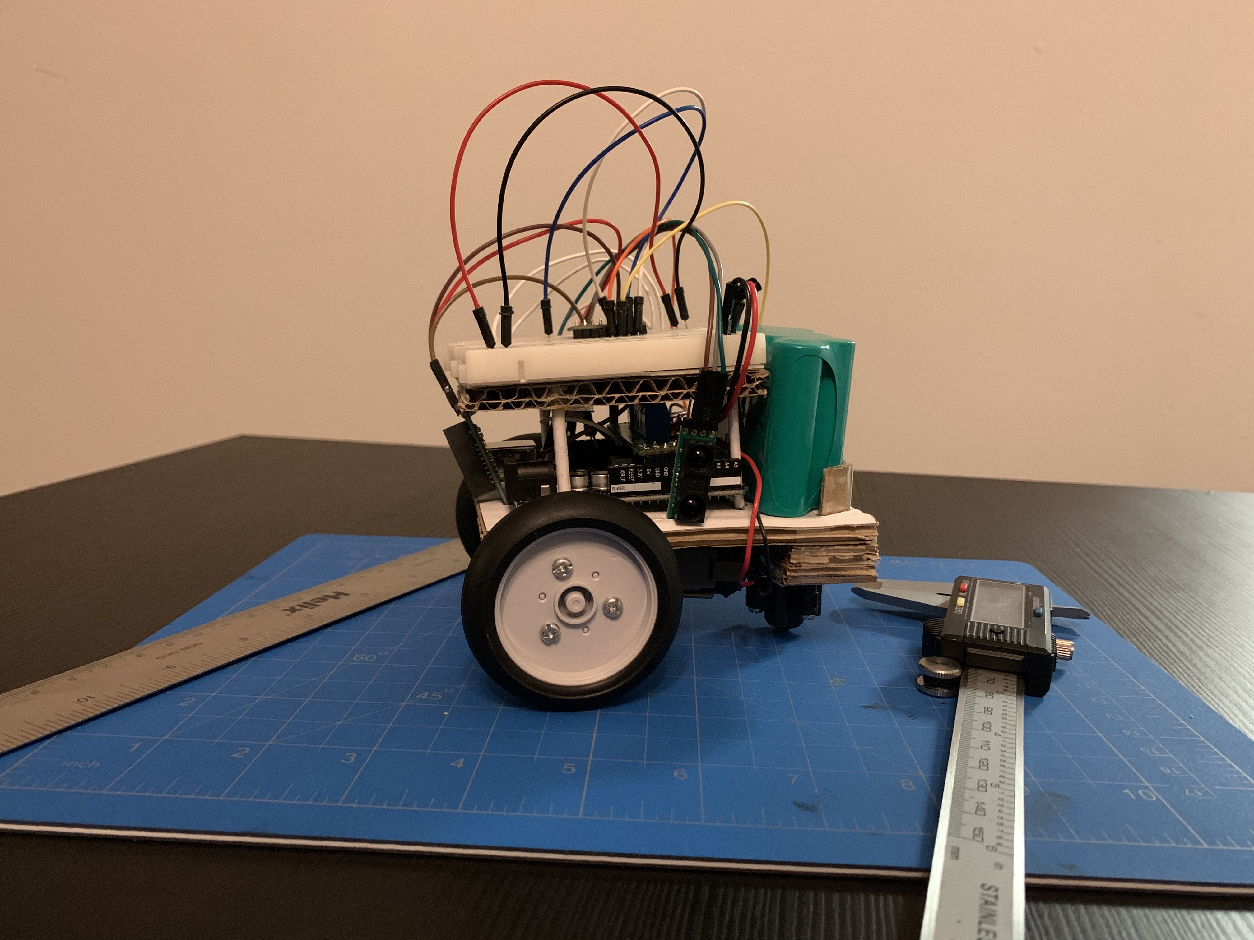
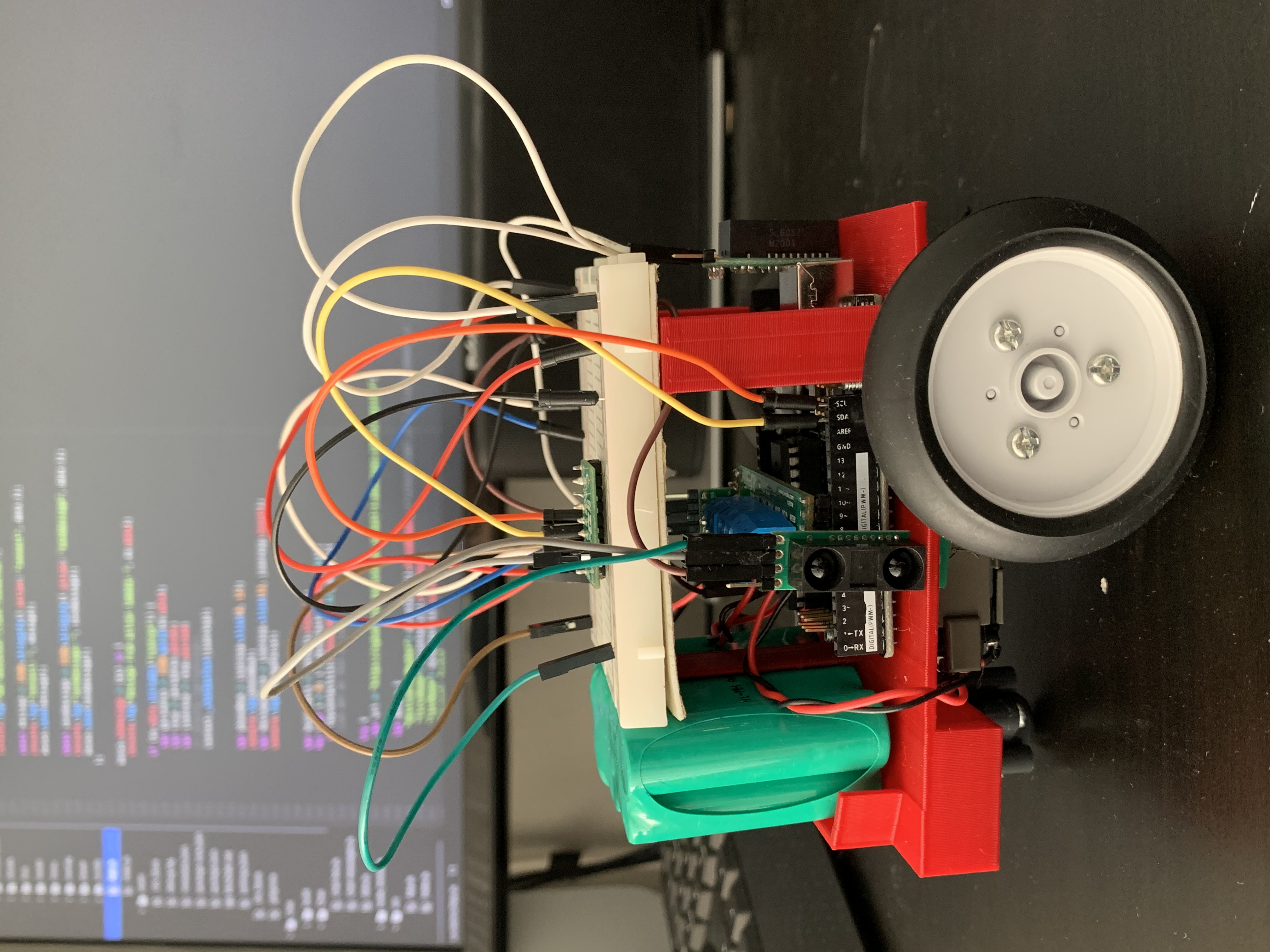
Today, I started to work on building the foundation of my robot. I attempted building a potential design for how my robot would be structured. I planted my breadboard, Arduino, motor driver and battery onto the foundation to estimate the amount of space that was going to be needed to support the components. To build a stable chassis, I had to adjust the height of the ball caster so that the platform supporting the components would be flat instead of being slanted.
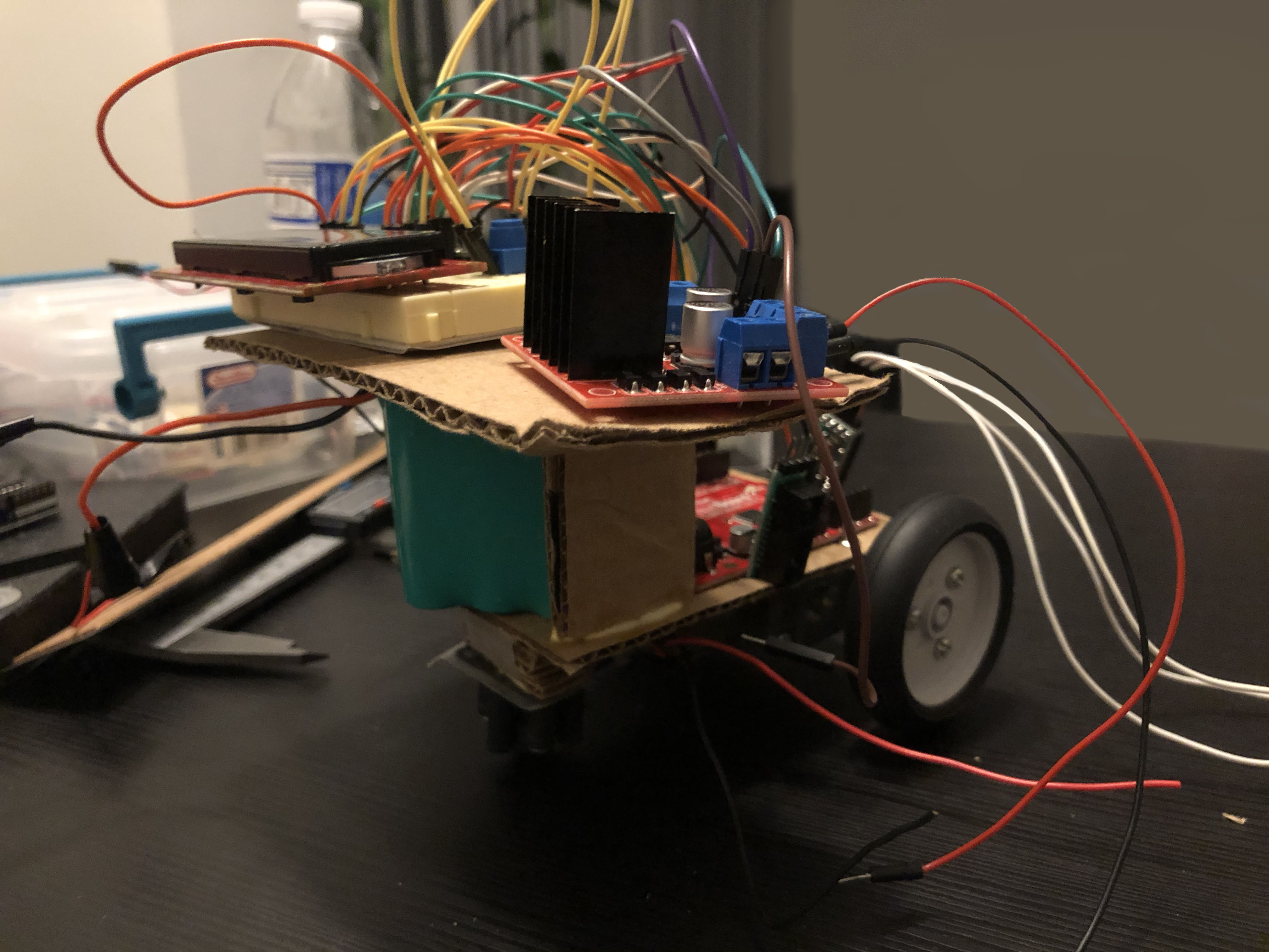
Today, I continued to work on the chassis. I decided to use cardboard once again as I could not find a software to utilize my 3D-printer for this project. During the build process of my second chassis, I used specific measurements to stabilize the Arduino board as the center. I then placed the breadboard and battery around the Arduino so that I would still be able to connect the wires. By building the chassis in this form, I would be able to have better wire management and greater stability while the robot is moving around.
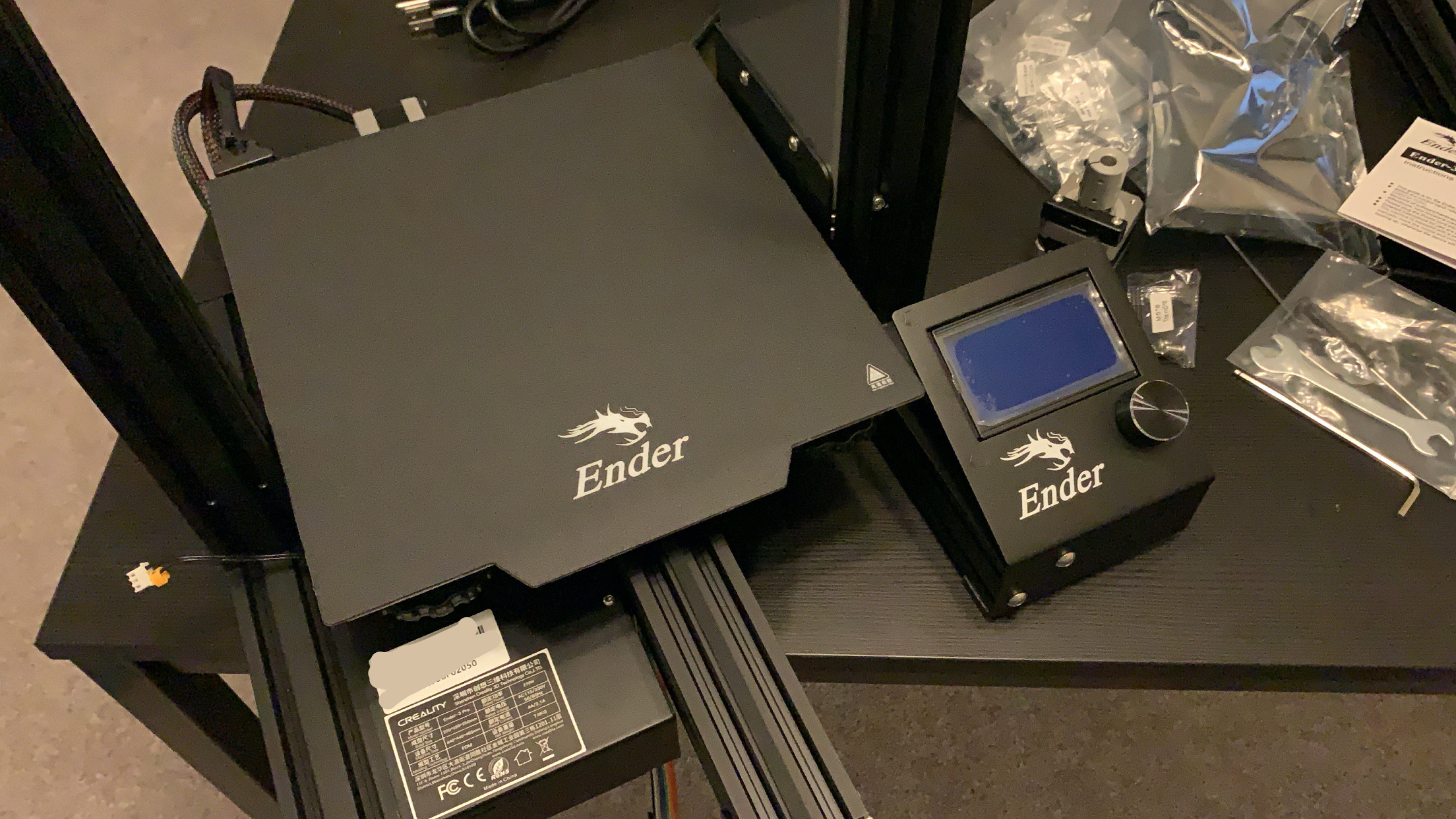
We purchased a 3D printer. We are using the Creality Ender 3 Pro 3D printer for our robot endeavors
Learning how to 3D model using a variety of softwares including TinkerCad and Fusion360
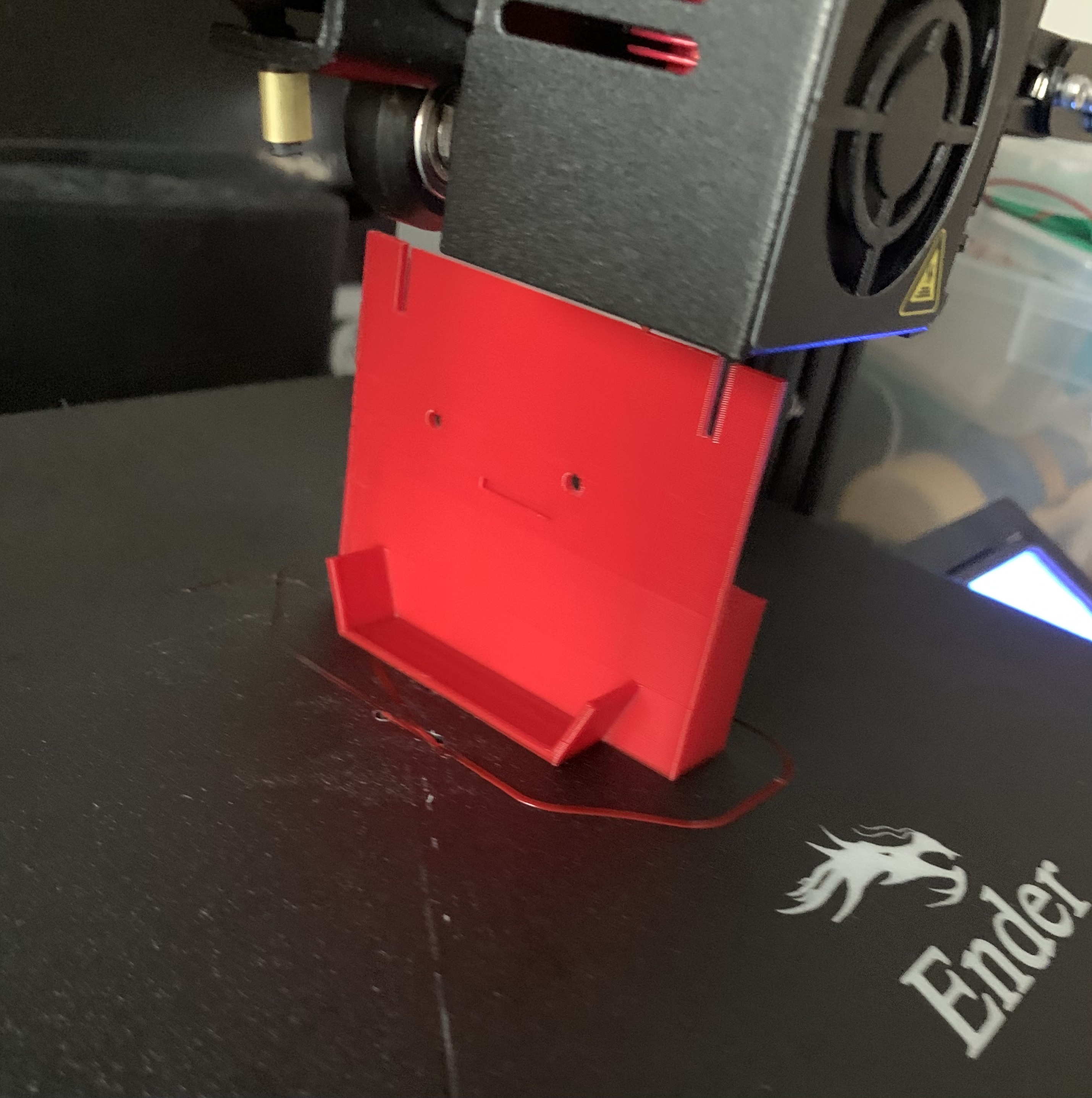
3D Printed Robotic Chassis with what I had built previously
Building a flex sensor based robot, based on what I experimented with earlier in August, I want to make a motor move based on how much I flex the softpot sensor.

Embedding a softpot flex sensor into a glove to mimic hand movements based on a clenched fist or open palm.

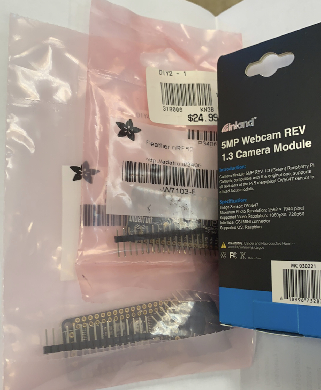
Waiting on my new components. I want to downsize my micromouse robot into a smaller part. To contribute to the size difference, I will be using the Adafruit Bluefruit microcontroller with an adapted DC motor controller shield for easier connection. However, unfortunately, I do not have the necessary stacking headers to complete this project at this time.
I will be taking a short hiatus to work on college applications! Wish me luck.
Thanks to all the stuff we bought for Thanksgiving and Black Friday, I made a small maze for my robot!

Spending some time to work on my robot again. I soldered the headers on the robot with the new microcontroller. This time I'll try to get it moving in a straight line. I'll need to purchase a battery if I want it to not be tethered to my computer.

Winter break couldn't have come sooner! I havent purchased the battery yet, but it seems to be able to meander through the cardboard maze pretty well. So far it's moving properly, it's not really accurate when it detects a maze opening.
My "algorithm" will turn left at every chance that it gets. Check out the video below for the full maze solving feature! I really tried and it seems to be working properly.

I'm looking into more advanced pathfinding algorithms based on what was shown here https://www.alexhadik.com/work/micromouse/. I think the flood fill algorithm is really interesting, but it's also really complicated. Hopefully I can understand this soon, but I don't think I would be for the time being. I think I need to learn more about recursion to better understand this concept.