

The robot consists of:
- 4 limbs with 3 degrees of freedom powered by hobby servos, with a leg extension of approximately 20cm.
- A 5000mah battery - 30 minutes of run time (optional).
- A 9-axis accelerometer/gyro sensor. (optional)
- A current and voltage sensor. (optional)
- A microcontroller (ESP32s) to communicate with Hardware and sensors.
- A single-board computer (RPi4) to compute image, location, ROS and advanced controller algorithms. (optional)
- 1.8 kg
This robot was inspired by the Kangal, SpotMicro and Open Quadruped. The concept was to have the best parts of all designs and make it compatible with SpotMicro parts. The current cost of the robot is around £250.


Click here for 3D printer parts, assembly instructions and bill of materials.
Yertle is a fusion of the leg design of Kangal and the body of SpotMicro. As such, you can use the control software and electronics from any Kangal or derivative with this robot (with a little modification). Any Modifications for the spot micro shell will also work with this robot. And You can exchange the legs for Kangal's if you want.
I have built a few quadruped robots and there are plenty of interesting leg mechanics to choose from. Overall The Kangal legs do have limitations. Such as their limited range in motion. But they do have the benefit of being extremely light and easy to change. This means I'm not pulling up anything heavy when I'm lifting my leg allowing the servos to be slightly faster when not under load. And I'm less worried about breaking them or putting the robot in a more extreme environment.

Click here for an electronics and wiring explanation.
I'm currently working on a better description of my wiring. I have soldered a custom Hat from my RPi that had all the necessary components. The robot was originally designed to use just the RPi but I found it to be unreliable as it is more complex to reset the device and more prone to corruption. As The ESP32 has WiFi I can debug the device remotely without a complex startup/shut down routine.
If you are familiar with wiring Kangal and the body of SpotMicro. You can use the same wiring.
Click here for the software.
The software runs in a master/slave system over the serial port or UPD over WiFi. The robot firmware acts as the slave. It controls all sensors, servos, computes the inverse kinematics of the robot and calculates safety limits. The main control system is written in Python3. It acts as a master It takes all data from the robot sensors and ROS(todo), generates the walk and sends this to the Slave.
The firmware was written in C++ using Arduino IDE so you can modify it to work on a different microcontroller if you want.
The Python Control software uses a GUI and can run on anything that has WiFi, a screen and can run Python3, including android devices(not tested).
The software can also runs ROS nodes for ROS2 integration(todo).
Click here for simulation tools.
There is a simulation built into the python software. It enables you to test movement with the controller without a robot.

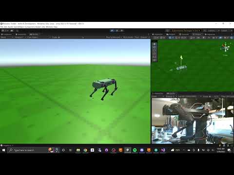
Here is another simulation example from Carter James using Unity.
- ROS integration