This project is a continuation of the DDS generator project, which I did on the STM32F401.
Please be careful, the project is still under development.
The purpose of this project is to create a small educational project based on the STM32 microcontroller using the HAL library, and also, writing a library of the AD9833 chip for experience.
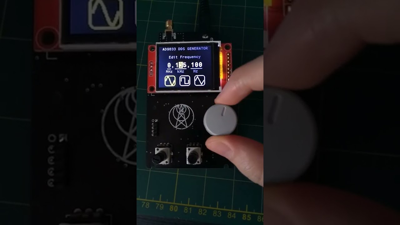
A simple signal generator on the AD9833 chip, which is a DDS generator of different waveform and frequency. The maximum frequency of the output signal is 12.5 MHz with a reference signal frequency of 25 MHz. The STM32G030F6P6TR microcontroller is used to control the DDS generator. A TFT display with a diagonal of 1.8 inches is used to display information. To conrtor the microcontroller, I used an encoder with hardware filtering on a Schmidt trigger. As well as two variable resistors for adjusting the amplitude and offset of the output signal. The device is powered by an external voltage source of 12-24 V.

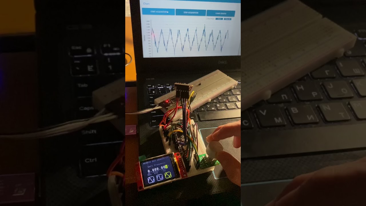
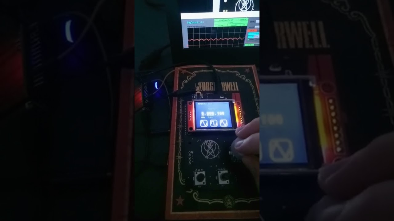
At the moment I can't test this on an oscilloscope, so I'm using an arduino oscilloscope

To obtain +12V -12V voltage for the output amplified signal of the generator, I used the simplest converter circuit from unipolar to bipolar power, built on a voltage divider with a common point, and zero stabilization using an operational amplifier and transistors.
Digital and analog ground are separate to reduce output signal noise.
Amplification and offset of the signal is performed by introducing variable resistors into the feedback loop of the operational amplifier. According to the principle of operation of the DDS generator and the Nyquist theorem, the maximum frequency of generation is 12.5 MHz for a sinusoidal signal, however, such a signal is not suitable for use.

For this, an LC filter of order 7 with a cutoff frequency of 12 MHz was calculated.

We have a signal without distortion and amplitude reduction, up to 5 MHz.


  hspi1.Instance = SPI1;
  hspi1.Init.Mode = SPI_MODE_MASTER;
  hspi1.Init.Direction = SPI_DIRECTION_2LINES;
  hspi1.Init.DataSize = SPI_DATASIZE_8BIT;
  hspi1.Init.CLKPolarity = SPI_POLARITY_LOW;
  hspi1.Init.CLKPhase = SPI_PHASE_1EDGE;
  hspi1.Init.NSS = SPI_NSS_SOFT;
  hspi1.Init.BaudRatePrescaler = SPI_BAUDRATEPRESCALER_2;
  hspi1.Init.FirstBit = SPI_FIRSTBIT_MSB;
  hspi1.Init.TIMode = SPI_TIMODE_DISABLE;
  hspi1.Init.CRCCalculation = SPI_CRCCALCULATION_DISABLE;
  hspi1.Init.CRCPolynomial = 7;
  hspi1.Init.CRCLength = SPI_CRC_LENGTH_DATASIZE;
  hspi1.Init.NSSPMode = SPI_NSS_PULSE_ENABLE;
Redefine SPI PORT if necessary in st7735.h file
#define ST7735_SPI_PORT hspi1 hspi2.Instance = SPI2;
hspi2.Init.Mode = SPI_MODE_MASTER;
hspi2.Init.Direction = SPI_DIRECTION_2LINES;
hspi2.Init.DataSize = SPI_DATASIZE_8BIT;
hspi2.Init.CLKPolarity = SPI_POLARITY_HIGH;
hspi2.Init.CLKPhase = SPI_PHASE_1EDGE;
hspi2.Init.NSS = SPI_NSS_SOFT;
hspi2.Init.BaudRatePrescaler = SPI_BAUDRATEPRESCALER_2;
hspi2.Init.FirstBit = SPI_FIRSTBIT_MSB;
hspi2.Init.TIMode = SPI_TIMODE_DISABLE;
hspi2.Init.CRCCalculation = SPI_CRCCALCULATION_DISABLE;
hspi2.Init.CRCPolynomial = 7;
hspi2.Init.CRCLength = SPI_CRC_LENGTH_DATASIZE;
hspi2.Init.NSSPMode = SPI_NSS_PULSE_ENABLE;Redefine SPI PORT if necessary in AD9833.h file
#define AD9833_SPI_PORT hspi2Enable "Combined Channels" to Encoder Mode in any Timer. The default settings are fine.
Edit TIM PORT definition in encoder.h
#define ENC_TIM_PORT htim3I ran into an out-of-memory problem because STM32G030 has only 32KB of FLASH memory. This is quite small when using the HAL library.
So I used cuz original sprintf weight too much.
I also selected Optimization level to -Os that means optimize for size.
After that I was able to compile the code.

You can find in repository.
Electronic components cost about $15. The PCB's cost $2 for 5 pieces and $10 for shipping.
Total cost: around $30
- Make PCB board
- Add oscilloscope measurements
- Add Sweep mode
- Add Noise mode
The following project is shared "as is", with the sole objective of being useful. The creator of the described piece of hardware and its associated software cannot guarantee its correct functioning under any circumstance. The author of this project will not be held responsible for any material, personal or economic losses to you or any third parties that may arise from using this design. This project will not be used under any circumstances on systems whose responsibility is critical, or from which people's lives depend upon, directly or indirectly.