https://www.youtube.com/watch?v=sPjZSRCmt1U
Name: Pamela Sabio
Student number: C14484542 DT282/2
Contact: c14484542@mydit.ie
Name: Eryk Szlachetka
Student number: C14386641 DT282/2
Contact: c14386641@mydit.ie
- Objective
- Resources
- To do
- Section 1: Hardware
- Section 2: Assembly
- Section 3: Arduino Code
- Section 4: Java Code
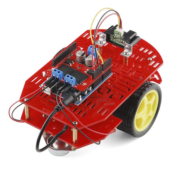
- The objective is to build and program an AI robot which can avoid obstacles, by making decisions on its own.
The project will also implement Bluetooth Control using Processing IDE.
The robot can also be controlled using a head set that reads your brainwaves.
Arduino Library: https://www.arduino.cc/en/Reference/HomePage
Getting Started with Arduino: https://www.arduino.cc/en/Guide/HomePage
New Ping Library: https://bitbucket.org/teckel12/arduino-new-ping/wiki/Home (For Distance Sensor)
- Order Hardware
- Assembly
- Arduino: Program distance sensor
- Arduino: Program AI
- Arduino: Program headSet
- Arduino: Program blueTooth control
- Make Arduino communicate with Processing using Bluetooth
Arduino board (Arduino UNO ATMEGA328P R3 € 26.98)
- A small programmable computer which acts as the head of the robot, allowing us to control its behaviours.

Distance sensor (HC-SR04 Ultrasonic Sensor € 4.49)
- A sensor which measures the distance from the nearest objects by sending and recieving waves. This sensor allows us to program the robot to take appropriate action if there is an obstacle within the range.

AWG Jumper Wires (HC-SR04 Ultrasonic Sensor € 4.95)
- Wires are used to connect different components together.

Bluetooth to serial slave
- Small device which can be pluged into the robot and be programmed to controll the robot remotely e.g. using an android app.

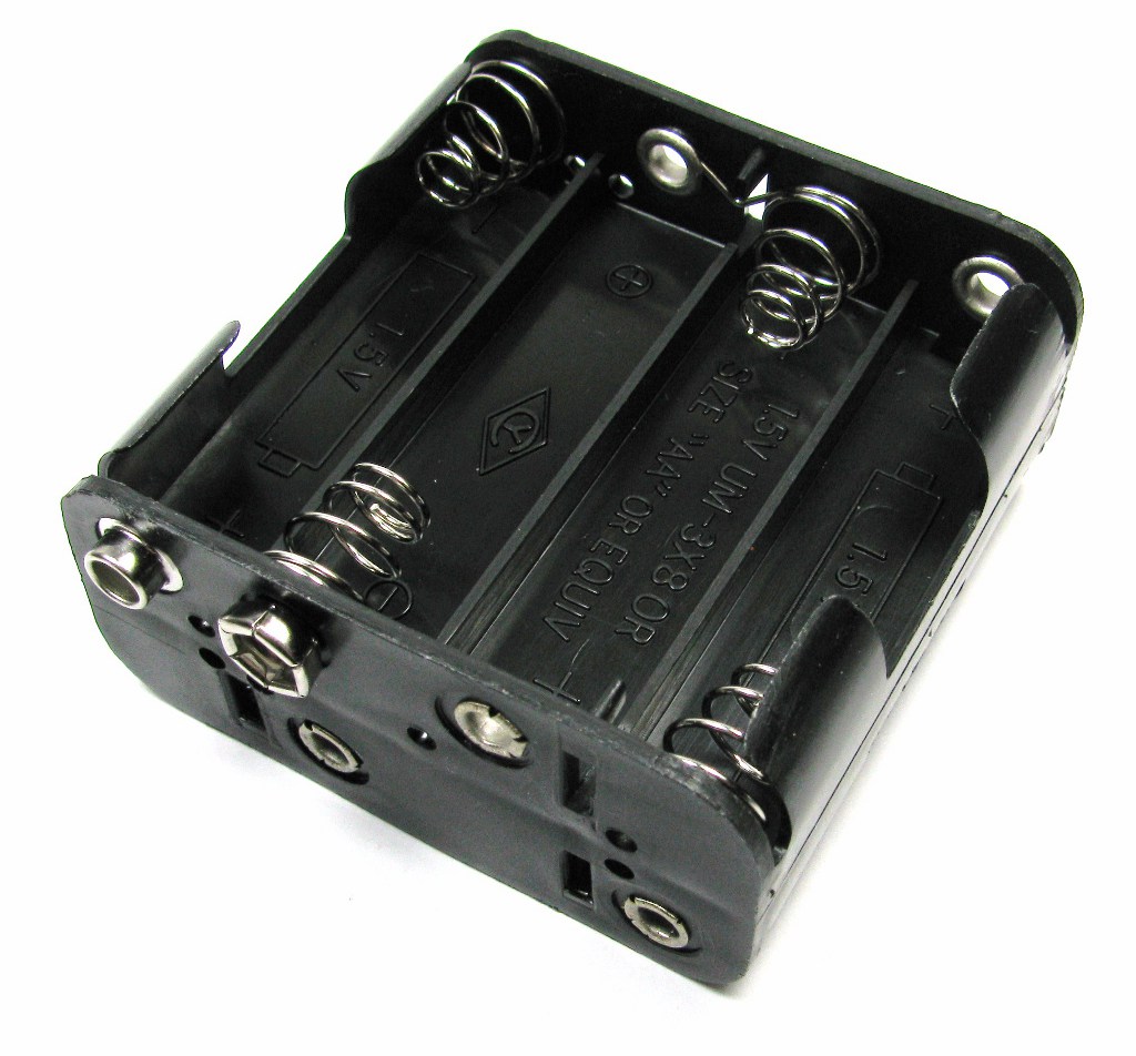
Battery holder (€ 1.29)
- Robots, like humans need energy in order to operate, they consume their energy from batteries. Battery box allow as to connect the batteries to the device.
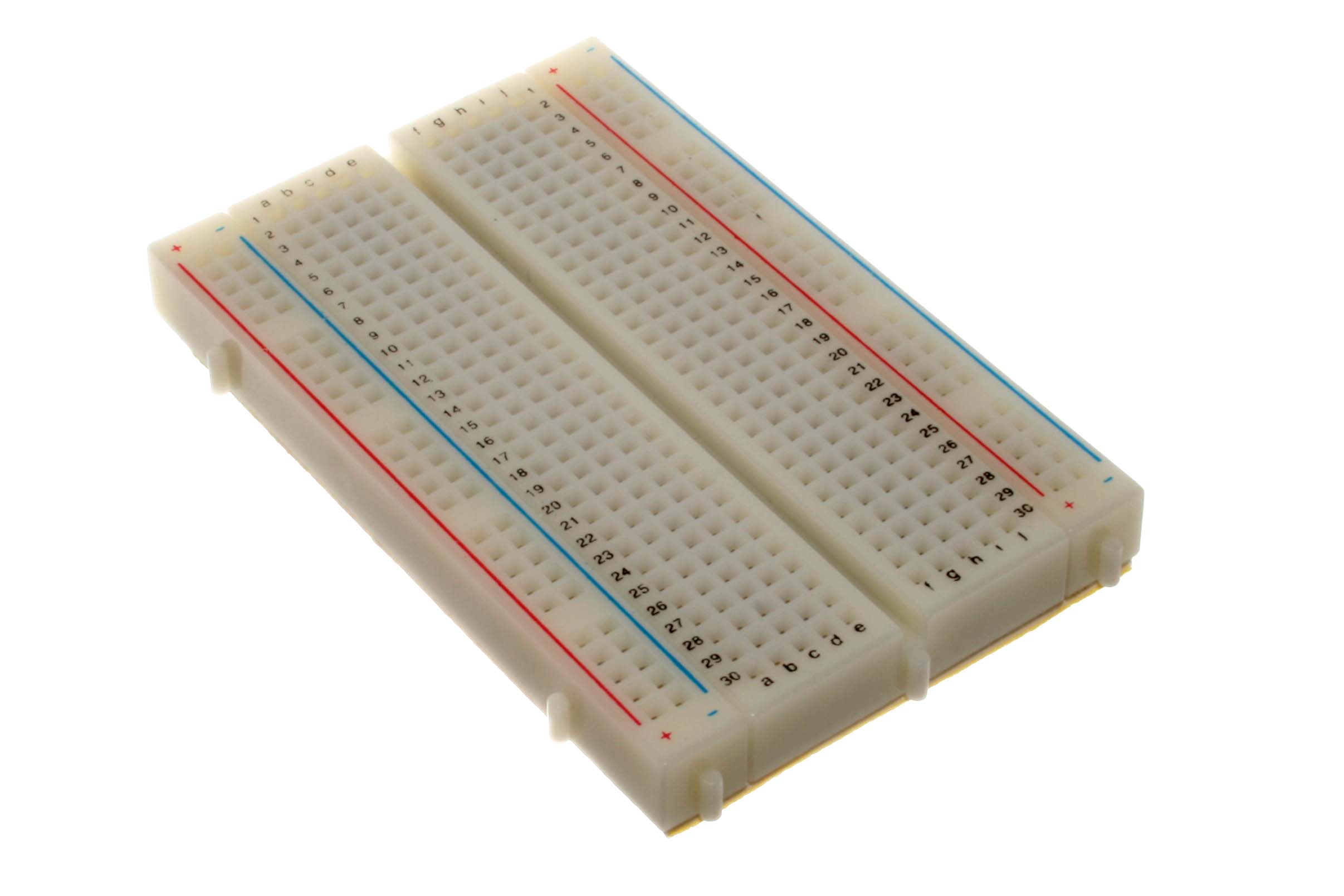
Prototyping board (€ 5.95)
- Prototyping board plays an unique part in planning stage.
Motor controller (Arduino Motor Shield R3 € 44.00)
- Controller which allows us to control the motors of the vehicle kit, neceserry in order to program/controll the speed and turnings of the robot.
Vehicle kit (Magician Chassis € 44.00)
- The base for the robot, which includes motors and wheels, supports the rest of hardware, compiled together forms a fully operational robot.
##Optional Muse HeadBand (€330)
- A device which can be connected via bluetooth, the device reads different brain waves and sends it over to your laptop, in this case it will allow us to move the robot with concetration level and turn the robot when user titlts the head thanks to accelerometer which is build into the device.

Components
- These are the components of the vehicle kit : the plastic chassis, wheels, motors, battery box and screws. It also comes with a manual and we followed that step-by-step in order to build this vehicle.

Bottom Chassis
- First we worked on assembling the bottom part of the vehicle which are the wheels, omni wheel and the motors. To setup the wheels we first connected the speed holder with wheel rotator of the motors and then attached it on the bottom chassis using the little plastice studs. After the motors are attached, we then push the wheels onto the speed holder. Next we mounted the omni wheel at the front (use the end 2 of the 4 holes in a line).

Top Chassis
- Then we assembled the top part by connecting the top chassis with spacers and screws to the bottom chassis. Use the two holes at the corner in the straight end of the bottom chassis and then use the very last two T-shaped holes in the curved end of the bottom chassis.

Mounting hardwares onto the vehicle
- We then mounted the other hardwares into the vehicles such as the arduino board, motor shield, breadboard, distance sensor and bluetooth sensor. The manufacturer suggests attaching the battery box to the bottom chassis, but to avoid the hassle of unscrewing the top to change the batteries, we have attached the box to the top platform. We just mounted the motor shield on the arduino board and connected all the wires to the motor shield. If you have a different motor shield, the wires should be connected to the arduino board.

Connecting wires
- The last step is connecting all the wires from the arduino or motor shield to the breadboard and the motors and then putting on the battery. The robot is now set for programming.

- In our Arduino we are going to have five classes stored in separate files with .h extensions ( headers ):
- distanceSensor.h (Base class for the sensors
- NewPingSensor.h (Class used to control UltraSonic sensors using newPing library)
- AiClass.h (Class that stores methods for Artificial Intelligence)
- HeadSet.h (Class used for controlling the robot with the HeadSet)
- erpam (The main class)
-
This class is used as a base class for sensor drivers, if you want to use another library for your sensor then all you have to do is write a driver for your sensor and extend this class.
The class has a protected int variable which means only this class and the subclasses can use this variable
protected: unsigned int maxDistance;
The code for the base class:
  namespace ErpamBot
  {
  class SensorDriver
  {
    protected:
      unsigned int maxDistance;
    public:
      SensorDriver(unsigned int distance) : maxDistance(distance){}
      virtual unsigned int getDistance();

  };

  };
- This class is used to control the UltraSonic sensors, the class implements two methods getDistance() and getMedian()
The class has a private field of type NewPing called sensor, which is the variable we are going to refer to in order to receive data from the sensor. The constructor accepts three parameters, the triggerPin, echoPin and the maxDistance, which are going to be passed in the main class.
private:
    NewPing sensor;
  public:
    NewPingSensor(int triggerPin, int echoPin, unsigned int maxDistance)
      : SensorDriver(maxDistance),
        sensor(triggerPin, echoPin, maxDistance)
    {
    }
The maxDistance is passed to the base class SensorDriver (distanceSensor.h)
: SensorDriver(maxDistance),
The sensor variable is initialized with the pins and maxDistance
sensor(triggerPin, echoPin, maxDistance)
This method returns distance from the obstacle in cm
    virtual unsigned int getDistance()
    {
      int distance = sensor.ping_cm();

      if (distance <= 0 )
      {
        return maxDistance;
      } else
      {
        return distance;
      }
    }
Distance variable is storing the distance from the obstacle in cm using the method called from new ping library 'ping_cm()'
int distance = sensor.ping_cm();
Then we are making sure there are no errors by checking if the distance returned is less than 0
if (distance <= 0 )
{
   return maxDistance;
}
This method returns median from 5 sensors scans which are NOT in cm .
virtual unsigned int getMedian()
    {
      int median = sensor.ping_median(5);
      int cm = sensor.convert_cm(median);


      if (cm <= 0 )
      {
        return maxDistance;
      } else
      {
        return cm;
      }

    }
This time we are storing the median instead of just the distance and converting it to cm, the reason for that is that sometime the sensors may read a wrong value, consider the example:
Sensor Data:
cm: 30
cm: 29
cm: 28
cm: 0       << ---
cm: 29
cm: 30
cm: 29
If the sensor will return a 0 when it shouldn't it can introduce chaos to the AI function, therefor if we get the median of the 5 values, 0 will lower the median, but the result will be still acceptable.
/* Driver for newPing sensor */
#include "distanceSensor.h"
namespace ErpamBot
{
class NewPingSensor : public SensorDriver
{
  private:
    NewPing sensor;
  public:
    NewPingSensor(int triggerPin, int echoPin, unsigned int maxDistance)
      : SensorDriver(maxDistance),
        sensor(triggerPin, echoPin, maxDistance)
    {
    }

    virtual unsigned int getDistance()
    {

      int distance = sensor.ping_cm();

      if (distance <= 0 )
      {
        return maxDistance;
      } else
      {
        return distance;
      }
    }

    virtual unsigned int getMedian()
    {
      int median = sensor.ping_median(5);
      int cm = sensor.convert_cm(median);


      if (cm <= 0 )
      {
        return maxDistance;
      } else
      {
        return cm;
      }

    }
};
};
- This class is used to control the motors, the class implements five methods: go_forward(), go_backward(), brake(), go_left() and go_right()._
Each method will set different speed to the motors in order to achieve its goal. The constructor is empty, as there is nothing to pass or initialize in the method.
This method, first releases the brakes by writing LOW to pins 9 and 8.
Then we are settings the direction to forward by writing HIGH to pins 12 and 13.
Finally we are writing the speed in this case 250 to pin 11 which is the right motor and 200 to pin 3 which is the left motor.
The speed depends from the motors we have, once of our motors runs slower therefore the difference when writing the speed.
void go_forward()
    {
      //brake
      digitalWrite(9, LOW); //left
      digitalWrite(8, LOW); //right

      //direction
      digitalWrite(12, HIGH); //left
      digitalWrite(13, HIGH); //right

      //speed
      analogWrite(11, 250); //right
      analogWrite(3, 200); //left

    }
In this method we release the brakes in the same way as in method above, by writing LOW to pins 9 and 8.
We are settings the direction to backward by writing LOW to pins 12 and 13.
Finally we are writing the speed in this case 230 for right motor and 200 for left motor.
void go_backward()
    {
      //direction
      digitalWrite(12, LOW); //left
      digitalWrite(13, LOW); //right

      //brake
      digitalWrite(9, LOW); //left
      digitalWrite(8, LOW); //right

      //speed
      analogWrite(3, 200); //left
      analogWrite(11, 230); //right
    }
In this method we turn on the brakes by writing HIGH to pins 9 and 8.
We are also setting the speed to 0 by writing it to pins 3 and 11.
void brake()
    {
      //speed
      analogWrite(3, 0); //left
      analogWrite(11, 0); // right

      //brake
      digitalWrite(9, HIGH); //left
      digitalWrite(8, HIGH); //right
    }
In order to turn left we have to manipulate the direction of the two motors, we can do it by changing it to opposite direction by writing LOW to pin 12 which is the left motor, and HIGH to pin 13 which is the right motor.
If the right motor goes forward and the left motor goes backward, the robot will turn left in place by 90 degrees.
Note that if we call this function the motor will keep turning unless we stop it.
void turn_left()
    {
      //direction
      digitalWrite(12, LOW); //left
      digitalWrite(13, HIGH); //right

      //brake
      digitalWrite(9, LOW); //left
      digitalWrite(8, LOW); //right

      //speed
      analogWrite(3, 200); //left
      analogWrite(11, 220); //right
    }
This method works almost the same way as turn_left() with the difference that we change the left motor to go forward and the right motor to go backward. Note that if we call this function the motor will keep turning unless we stop it.
void turn_right()
    {
      //direction
      digitalWrite(12, HIGH); //left
      digitalWrite(13, LOW); //right

      //brake
      digitalWrite(9, LOW); //left
      digitalWrite(8, LOW); //right

      //speed
      analogWrite(3, 200); //left
      analogWrite(11, 220); //right
    }
So by now our code should look like this:
// Class for AI
namespace ErpamBot
{
class AiClass
{
  public:
    AiClass() {} // Constructor

    void go_forward()
    {
      //brake
      digitalWrite(9, LOW); //left
      digitalWrite(8, LOW); //right

      //direction
      digitalWrite(12, HIGH); //left
      digitalWrite(13, HIGH); //right

      //speed
      analogWrite(11, 250); //right
      analogWrite(3, 200); //left

    }

    void go_backward()
    {
      //direction
      digitalWrite(12, LOW); //left
      digitalWrite(13, LOW); //right

      //brake
      digitalWrite(9, LOW); //left
      digitalWrite(8, LOW); //right

      //speed
      analogWrite(3, 200); //left
      analogWrite(11, 230); //right
    }

    void brake()
    {
      //speed
      analogWrite(3, 0); //left
      analogWrite(11, 0); // right

      //brake
      digitalWrite(9, HIGH); //left
      digitalWrite(8, HIGH); //right
    }

    void turn_left()
    {
      //direction
      digitalWrite(12, LOW); //left
      digitalWrite(13, HIGH); //right

      //brake
      digitalWrite(9, LOW); //left
      digitalWrite(8, LOW); //right

      //speed
      analogWrite(3, 200); //left
      analogWrite(11, 220); //right
    }

    void turn_right()
    {
      //direction
      digitalWrite(12, HIGH); //left
      digitalWrite(13, LOW); //right

      //brake
      digitalWrite(9, LOW); //left
      digitalWrite(8, LOW); //right

      //speed
      analogWrite(3, 200); //left
      analogWrite(11, 220); //right
    }

};
};
-
This class is the main class and this is where we are going to declare and initialize global variables, call and manipulate the classes named above.
This is also where we are opening the serial port in order to connect via Bluetooth.
These are the libraries that we need to include:
- stdlib.h which is the header of the general purpose library which includes functions involving memory allocation, process control, conversions and others.
- SoftwareSerial.h to allow serial communication on other digital pins of the Arduino which in our case is the Bluetooth sensor.
- NewPing.h which is the library used in order to use different functions for the Ultrasonic distance sensor.
In C++ we need to include the header files in the main when creating different classes thus, the HeadSet.h, AiClass.h and NewPingSensor.h are included.
#include <stdlib.h>
#include <SoftwareSerial.h>
#include <NewPing.h>
#include "HeadSet.h"
#include "AiClass.h"
#include "NewPingSensor.h"
These are the constant variables that we are defining:
//Variables for AI
#define CLOSE 45
#define TOO_CLOSE 40
#define MAX_DISTANCE 200
//Front sensor pins
#define TRIGGER_PIN 6
#define ECHO_PIN 7
//Left sensor pins
#define LT_PIN 4
#define LE_PIN 5
//Right sensor pins
#define RT_PIN 2
#define RE_PIN 10
The first three variables are used for the AI function.
The following variables are used for initializing the three ultrasonic sensors that we are using. The values represent the pins that we are using in the arduino for each sensor.
Here we are using namespace, initializing the instance of the classes and the SoftwareSerial library.
using namespace ErpamBot;
using namespace std;

// Initialize the three sensors
NewPingSensor distanceSensor(TRIGGER_PIN, ECHO_PIN, MAX_DISTANCE);
NewPingSensor sensorLeft(LT_PIN, LE_PIN, MAX_DISTANCE);
NewPingSensor sensorRight(RT_PIN, RE_PIN, MAX_DISTANCE);

AiClass ai;
HeadSet hs;

SoftwareSerial BTserial(0, 1);
Namespaces are used to organize code into logical groups and to prevent name collisions that can occur especially when your code base includes multiple libraries.
When you make a call to using namespace namespace_name, all symbols in that namespace will become visible without adding the namespace prefix. A symbol may be for instance a function, class or a variable.
Because we are using the namespace ErPamBot in all our classes and the built in C++ library routines are kept in the standard namespace (that includes stuff like cout, cin, string, vector, map, etc.) and these tools are used so commonly, we want to call a using declarations in order to avoid typing ErPamBot:: and std:: prefixes constantly.
using namespace ErPamBot;
using namespace std;
When initializing the distance sensor we are passing three parameters: Echo Pin, Trigger Pin and Max Distance. The parameters that we are passing are the constant parameters that we have defined.
NewPingSensor distanceSensor(TRIGGER_PIN, ECHO_PIN, MAX_DISTANCE);
The Arduino hardware has built-in support for serial communication on pins 0 and 1 hence why we are using these values when initializing the SoftwareSerial library.
SoftwareSerial BTserial(0, 1);
These are all the global variable that we are using in the program. We are setting these variables as global because we want all the functions to be able to access these variables.
String BluetoothData; // Stores data sent via bluetooth
String acc = ""; // Stores data from headset's accelerometer
int choice = 0; // Variable for menu
boolean go = false;
boolean brakeFlag = false;

// Variables used by the sensors
unsigned int cm = 0;
unsigned int median = 0; // Front sensor
unsigned int medianLeft = 0; // Left sensor
unsigned int medianRight = 0; // Right sensor

//Variables to be used only if ONLY ONE SENSOR is connected
int obstacleRight = 0;
int obstacleLeft = 0;
We put code here in the setup because we want the code to run once at the start.
Here we are configuring the specified pins to behave either as an input or an output. We are using pinMode which takes two parameters:
pinMode(pin, mode)
-
pin: the number of the pin whose mode you wish to set
-
mode: INPUT, OUTPUT, or INPUT_PULLUP. (see https://www.arduino.cc/en/Tutorial/DigitalPins for a more complete description of the functionality.)
 void setup() {
   // put your setup code here, to run once:
   BTserial.begin(9600);
   Serial.begin(19200);
   //Setup Channel A
   pinMode(12, OUTPUT); //Initiates Motor Channel A pin
   pinMode(9, OUTPUT); //Initiates Brake Channel A pin

   //Setup Channel B
   pinMode(13, OUTPUT); //Initiates Motor Channel A pin
   pinMode(8, OUTPUT);  //Initiates Brake Channel A pin

   // Set brakes at start
   digitalWrite(9, HIGH);
   digitalWrite(8, HIGH);

   //Setup UltraSonic sensor pins
   pinMode(TRIGGER_PIN, OUTPUT);
   pinMode(ECHO_PIN, INPUT);
   pinMode(LT_PIN, OUTPUT);
   pinMode(LE_PIN, INPUT);
   pinMode(RT_PIN, OUTPUT);
   pinMode(RE_PIN, INPUT);
 }
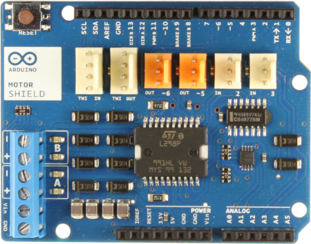
If you take a look at the photo below of the Arduino Motor Shield R3 which is the motor shield that we are using for this robot, it indicates what pins we are supposed to use for Motor A and Motor B.

As you can see, DIR stands for direction, PWM stands for Power Motor and there is also BRAKE. That is why we are using the values above in initiating Motor A and Motor B pins.
Therefore if we want to make the motors go forward, we are going to set pin 12 and 13 to HIGH and if we want to make it go backward the we are going to set it to LOW. Note that the we have to set the brakes (pins 8 and 9) to LOW every time we want the motors to move as we don't want to apply brakes. We also need to set the speed (pins 3 and 11) according to how fast we want the motors to run. Maximum speed is 250.
When we run the program first, we want to apply the brakes as we do not want the robot to be running its motors unless we tell it to do so therefore we are going to set both pin 8 and pin 9 to HIGH.
digitalWrite(9, HIGH);
digitalWrite(8, HIGH);
After creating a setup() function, which initializes and sets the initial values, the loop() function does precisely what its name suggests, and loops consecutively, allowing your program to change and respond. Use it to actively control the Arduino board.
void loop() {
  switch (choice)
  {
    case 1:
      bluetoothcontrol(BluetoothData);
      break;
    case 2:
      aifxn();
      break;
    case 3:
      headSetfxn();
      break;
  }
}
Here we are going to use a switch statement for calling different functions based on the variable choice which is depending on the data received via bluetooth through BTserial which I will be talking about in the next section.
This function is called automatically when data is available. This means that this function does not have to be called in main.
void serialEvent()
{
  if (BTserial.available())
  {
    BluetoothData = BTserial.readStringUntil(',');

    if (BluetoothData.startsWith("1"))
    {
      BluetoothData.replace("1", "");
      choice = 1;
    } else if (BluetoothData.startsWith("2"))
    {
      choice = 2;
    } else if (BluetoothData.startsWith("3"))
    {
      BluetoothData.replace("3", "");
      acc = "";
      if (BluetoothData.startsWith("A"))
      {
        acc = BluetoothData;
        acc.replace("A", "");
      }
      choice = 3;
      BTserial.flush();
    }
  }
}
First we get the number of bytes (characters) available for reading from the serial port. This is data that's already arrived and stored in the serial receive buffer.
if (BTserial.available()){}
After receiving data we then read the incoming byte from the serial buffer into an array and terminates after , is detected. We are storing this in BluetoothData.
BluetoothData = BTserial.readStringUntil(',');
We want to check whether the String that we have read starts with 1, 2 or 3 because this will determine the choice for the switch statement in the loop() function. In the example code below x is 1,2 or 3.
    if (BluetoothData.startsWith("x"))
    {
      BluetoothData.replace("x", "");
      choice = x;
    }
If BluetoothData starts with 3, then it means that we want to control the robot using the muse headset that reads brainwaves therefore we are storing the data of the accelerometer to the variable acc.
    else if (BluetoothData.startsWith("3"))
    {
      BluetoothData.replace("3", "");
      acc = "";
      if (BluetoothData.startsWith("A"))
      {
        acc = BluetoothData;
        acc.replace("A", "");
      }
      choice = 3;
      BTserial.flush();
    }
This function allows the robot to be controlled using W, A, S, D keys from the keyboard.
void bluetoothcontrol(String BluetoothData)
{
  if (BluetoothData.startsWith("L"))
  {
    BluetoothData.replace("L", "");
    float sSpeed = BluetoothData.toFloat();

    if (sSpeed > 0 )
    {
      digitalWrite(12, HIGH);

    } else if (sSpeed < 0)
    {
      digitalWrite(12, LOW);
      sSpeed *= -1;
    }

    digitalWrite(9, LOW);
    analogWrite(3, sSpeed);
  }

  if (BluetoothData.startsWith("R")) {

    BluetoothData.replace("R", "");
    float sSpeed = BluetoothData.toFloat();

    if (sSpeed > 0 )
    {
      digitalWrite(13, HIGH);

    } else if (sSpeed < 0)
    {
      digitalWrite(13, LOW);
      sSpeed *= -1;
    }

    digitalWrite(8, LOW);
    analogWrite(11, sSpeed);
  }
}
If BluetoothData is starting with L then it means the we are passing the speed of the left motor from processing so we are using pin 3 to set left motor speed. If it is starting with R then we are passing the speed of the right motor from processing so we are using pin 11 to set right motor speed. We are storing the speed in float variable called sSpeed
float sSpeed = BluetoothData.toFloat();
If sSpeed > 0 then that means that we want the motor to go forward hence why we are setting pin 12 or 13 to HIGH.
If sSpeed < 0 then that means that we want the motor to go backward hence why we are setting pin 12or 13 to LOW and we need to multiply sSpeed by -1 as we need a positive number.
As stated in the setup() section, we are going to set pin 8 or 9 to LOW if we want the motors to move.
This function just calls the go_forward() function from the HeadSet Class. We are converting the accelerometer data that we stored in acc and we are passing it to go_forward() function in HeadSet Class. We are going to manipulate all the data that we are receiving in the HeadSet class therefore not much codes are needed here.
void headSetfxn()
{
  float nacc = acc.toFloat();
  hs.go_forward(nacc);
}
This function is the function for Artificial Intelligence feature. We are going to make the robot move according to the data that the HC-05 distance sensors are receiving.
void aifxn()
{
  ai.go_forward();
  median = distanceSensor.getMedian();
  medianLeft = sensorLeft.getMedian();
  medianRight = sensorRight.getMedian();

  if(medianLeft < TOO_CLOSE / 5)
  {
    ai.turn_right();
    delay(50);
    ai.brake();
    ai.turn_left();
    delay(5);
  }else if (medianRight < TOO_CLOSE / 5)
  {
    ai.turn_left();
    delay(50);
    ai.brake();
    ai.turn_right();
    delay(10);
  }

  if (median < CLOSE * 2) // medianFront
  {
    ai.brake();
    delay(500);
    brakeFlag = true;
    if(median < TOO_CLOSE/5)
    {
      ai.go_backward();
      delay(200);
      ai.brake();
    }
  }
  else
  {
    brakeFlag = false;
  }

  if (brakeFlag)
  {
    checkObstacles();
    brakeFlag = false;
    go = false;
  }

  aifxn();
}
First thing the robot does is to go forward and gets the medians of the data from all the sensors.
  ai.go_forward();
  median = distanceSensor.getMedian();
  medianLeft = sensorLeft.getMedian();
  medianRight = sensorRight.getMedian();
We don't want to sides of the robot scratching the wall or other obtacles when it is going forward thus we are going to make it move slightly if the distance to the wall is too near.
If medianLeft is too near then we are turning the robot to the right for 50ms, brake and then left for 5ms so that it can turn back to the direction that it was originally facing.
If medianRight is too near the we are turning the robot to the left for 50ms, brake, and then right for the same reason as above. Notice that we are using 10ms here and 5ms in the previous if statement. This is because the powers in the motors are different therefore the motor speeds are set differently.
 if (medianLeft < TOO_CLOSE / 5)
 {
   ai.turn_right();
   delay(50);
   ai.brake();
   ai.turn_left();
   delay(5);
 } else if (medianRight < TOO_CLOSE / 5)
 {
   ai.turn_left();
   delay(50);
   ai.brake();
   ai.turn_right();
   delay(10);
 }
Now we are dealing with the front sensor which is also going to involve the left and right sensors. If median is close enough then we brake the motors and set brakeFlag to True (here we are setting it to CLOSE * 2 because the motors are running fast so to ensure that the robot won't bump into the obstacle, were setting the stopping distance further).
if the obstacle is very close, then the robot most certainly will hit the obstacle when turning left or right. To avoid this we are going to make it go backward for 200ms.
  if (median < CLOSE * 2) // medianFront
  {
    ai.brake();
    delay(500);
    brakeFlag = true;
    if (median < TOO_CLOSE / 5)
    {
      ai.go_backward();
      delay(200);
      ai.brake();
    }
  }
If there are no obstacles on the way then we are setting brakeFlag to False. That means that the robot can keep on going forward as it won't execute the if(brakeFlag) statement.
If brakeFlag is set to true, the we are calling the checkObstacles() function which is a function in charge of making decisions after detecting an obstacle in front. After that we are setting the brakeFlag to false because we only want to call the checkObstacles() once and it is when the robot has detected an obstacle from the front sensor.
We are then calling the function recursively as we want the function to run all the time. The only time we want this to stop is when we turn the program off.
  else
  {
    brakeFlag = false;
  }

  if (brakeFlag)
  {
    checkObstacles();
    brakeFlag = false;
    go = false;
  }

  aifxn();
This function is used in the aifxn() and is responsible for the necessary actions of the robot based on the scanned data from the HC-05 distance sensors. Note that this function is only called when the robot has detected an obstacle in front. We want to check the left and right sensors in order for the robot to decide which direction its taking next.
void checkObstacles()
{
  median = distanceSensor.getMedian();
  medianLeft = sensorLeft.getMedian();
  medianRight = sensorRight.getMedian();

  if (medianLeft < TOO_CLOSE && medianRight < TOO_CLOSE)
  {
    ai.go_backward();
    checkObstacles();
  } else if (medianLeft < TOO_CLOSE && medianRight > TOO_CLOSE)
  {

    ai.turn_right();
    delay(270);
  } else if (medianLeft > TOO_CLOSE && medianRight < TOO_CLOSE)
  {

    ai.turn_left();
    delay(220);
  } else if (medianLeft > TOO_CLOSE && medianRight > TOO_CLOSE)
  {
    int r = random(2, 10);
    if (r % 2 == 0)
    {
      ai.turn_left();
      delay(220);
    } else if (r % 2 != 0)
    {
      ai.turn_right();
      delay(270);
    }
  }
}
First it gets the median distance from the three distance sensors: Front, Left and Right. The robot will use these variables in order to make decisions.
  median = distanceSensor.getMedian();
  medianLeft = sensorLeft.getMedian();
  medianRight = sensorRight.getMedian();
If there are obstacles both in the left and the right of the robot, then we want the robot to reverse as there are no other places to go. We then want to call checkObstacles() function recursively in order for the robot to keep on reversing until there's no more obstacle in either left or right.
  if (medianLeft < TOO_CLOSE && medianRight < TOO_CLOSE)
  {
    ai.go_backward();
    checkObstacles();
  }
Otherwise, if there is an obstacle only in the left then we are going to make the robot turn 90 degrees to the right. This is done by turning it to the right for 270ms.
If there is an obstacle only in the right then we are going to make the robot turn 90 degrees to the left. This is done by turning it to the left for 220ms (We are turning them with different times due to the motor power difference).
  else if (medianLeft < TOO_CLOSE && medianRight > TOO_CLOSE)
  {

    ai.turn_right();
    delay(270);
  } else if (medianLeft > TOO_CLOSE && medianRight < TOO_CLOSE)
  {

    ai.turn_left();
    delay(220);
  }
If neither of the left sensor and right sensor has detected any obstacles, then we are making the robot turn left or right randomly as we want the robot to make its own decisions.
  else if (medianLeft > TOO_CLOSE && medianRight > TOO_CLOSE)
  {
    int r = random(2, 10);
    if (r % 2 == 0)
    {
      ai.turn_left();
      delay(220);
    } else if (r % 2 != 0)
    {
      ai.turn_right();
      delay(270);
    }
  }
- This class is for manipulating the robot based on the data that we are receiving from the accelerometer of the headset. How the accelerometer works is it is giving values based on how you are tilting your head (if you tilt your head to the left it will return negative values, and if you tilt your head to the right it will return positive values). The more you tilt your head, the bigger the value its gonna return for positive values, and the smaller the values for negative values.
This is the only method in this class. And in this class we are only changing the direction of the robot based on the accelerometer values the we are receiving. This value is passed as a parameter and we are calling it acc.
void go_forward(float acc)
Note that pin 12 and 13 is always set to HIGH and pin 8 and 9 is always set to LOW throughout the whole function because we want the motors to keep on running. We are only changing the direction by manipulating the values in pin 3 and pin 11.
If acc is less than -150, then we want the robot to turn left so we are setting pin 11 to 220 and pin 3 to 50. This is because if we want to turn the robot to the left then the right motor should be faster than the left motor.
        if (acc < -150)
        {
          digitalWrite(12, HIGH);
          digitalWrite(13, HIGH);

          digitalWrite(9, LOW);
          digitalWrite(8, LOW);

          analogWrite(11, 220); // RIGHT
          analogWrite(3, 50); // LEFT
        }
If acc is more than 150, then we want the robot to turn right so we are setting pin 11 to 50 and pin 3 to 200. The difference in values in the pins when turning left and right is due to the difference in motor power.
        else if (acc > 150)
        {
          digitalWrite(12, HIGH);
          digitalWrite(9, LOW);
          digitalWrite(13, HIGH);
          digitalWrite(8, LOW);

          analogWrite(11, 50); // RIGHT
          analogWrite(3, 200); // LEFT
        }
If acc is more the -150 and less than 150 then that means that our head is in neutral position so we want the robot to go straight so we are setting pin 11to 200 and pin 3 to 170. The left motor is more powerful than the right motor so we want to set the left motor with lower speed so that they will have the same speed.
        else if (acc > -150 && acc < 150 && acc != 0)
        {
          digitalWrite(12, HIGH);
          digitalWrite(9, LOW);
          digitalWrite(13, HIGH);
          digitalWrite(8, LOW);

          analogWrite(11, 200);
          analogWrite(3, 170);
        }
So by now, our code must look like this:
// Class for AI
namespace ErpamBot
{
class HeadSet
{

  private:

  public:
    HeadSet() {} // Constructor

    void go_forward(float acc)
    {
        if (acc < -150)
        {
          digitalWrite(12, HIGH);
          digitalWrite(13, HIGH);

          digitalWrite(9, LOW);
          digitalWrite(8, LOW);

          analogWrite(11, 220); // RIGHT
          analogWrite(3, 50); // LEFT
        } else if (acc > 150)
        {
          digitalWrite(12, HIGH);
          digitalWrite(9, LOW);
          digitalWrite(13, HIGH);
          digitalWrite(8, LOW);

          analogWrite(11, 50); // RIGHT
          analogWrite(3, 200); // LEFT
        } else if (acc > -150 && acc < 150 && acc != 0)
        {
          digitalWrite(12, HIGH);
          digitalWrite(9, LOW);
          digitalWrite(13, HIGH);
          digitalWrite(8, LOW);

          analogWrite(11, 200);
          analogWrite(3, 170);
        }
      }
};
};
- In order to run the java code we will need to download and import the following libraries into our IDE (The IDE that we use and recommend is IntelliJ)
- Processing core.jar(Standard library that comes with Processing IDE)
- Processing video (Standard library that comes with Processing IDE)
- Processing serial (Standard library that comes with Processing IDE)
- Processing controlP5
- oscP5
- In our Java Code we are going to have three classes stored in separate files with .java extensions:
- Main.java (The main class that manipulates other classes)
- RemoteControl.java (Class used to visualize the BT control)
- HeadSet.java (Class that visualizes the head set)
-
Main class is the class where we are going to establish our bluetooth connections with both arduino robot and the headset and initialize and manipulate classes.
-
The methods we are going to use in main are as follow:
- Settings - Used to set the screen size
- Setup - Used to initialize all that is to be executed only once at the start of the program
- Draw - A loop that is executed 60 times a second, used to constantly update our program
- MouseClicked - Used to handle the event when mouse is clicked
- Menu - Method to draw a menu for our program
- KeyPressed - Used to handle the event when key is pressed
- Turning - Used to turn the robot while in bluetooth control mode
- Acceleration - Used to set acceleration of the robot when in bluetooth control mode
- oscEvent - Event handler for the headset which recieves the data and takes appropriate action
If we have the libraries downloaded and added to our IDEA (How to add libraries in IntelliJ) then the first thing we are going to do is import those libraries using
importwhich will allow us to use or the methods or functions located in those libraries.package erpam; import processing.core.*; import processing.core.PImage; import processing.video.*; import processing.serial.*; import oscP5.*;Next we are declaring the global variables, which means we can access those variables from every method in the package.
The variable
myPortof a typeSerialwhich is a method imported from theprocessing.serial.*library, allow us to set up the bluetooth connection with the robot.
The variableBTis declared here as typeRemoteControl, which is one of our classes, so that means a variable BT is an instance of a class RemoteControl.Serial myPort; RemoteControl BT;Next, we are declaring variables for the menu,
PImageis a type of variable that allow us to store the image for the menu.choicewill be used to record which functionality the user chooses to use i.e. bluetooth control, headset control etc.
   PImage erpam;  // Menu image
   int choice = 0;         // User choice (menu)
The next, global variables are the variables used for both left and right motors and the current gear.
The variables for the motors are initialized to 0 as at the beging the motor speeds are 0.
Also the currentGear is set to N which stands for Neutral this will change depending if user is going forward or backward, then the gear will change to either D which stands for Drive or R which stands for Reverse
   float rightspeed = 0;   // Right speed of the motor
   float leftspeed = 0;    // Left speed of the motor
   char currentGear = 'N';
And the last variables we have to declare are the variables used for the headSet.
Note this is an optional step and if you are following along and don't feel like buying the headSet then ignore this code.
In order to establish connection with the headset, we have to turn on the headSet then pair it with your PC/Laptop bluetooth, and then open your terminal and use the command muse-io --device Muse --osc osc.udp://localhost:5000 to connect to it.
Please note the localhost:5000 at the end, which is the port number 5000, if you are using different port, make sure to change it in the setup() method where we are initializing the connections
The variable oscp5 of type OscP5 is imported from oscP5 library, which allows us for the connection with the headSet.
The next two variables cVar and aVar are float variables which store the data sent from the headSet (concetration and accelerometer data).
The variable checkA and checkcVar are used to compare the differences in recieved data later on.
Please note that the variable checkA is initialized to 800 at the start.
The passVar of type String is the variable we are going to use to pass the data to Arduino, the content of that variable will depend on the data we recieve from the headSet.
The variable headSet of type HeadSet is an instance of the HeadSet class, whenever headSet variable is used that means it refers to that class.
The last two variables pdir and sdir are the variables we are going to pass the the HeadSet method, will be explained in more detail when we get to the oscEvent method.
   // Use this code if HeadSet connected
   //  muse-io --device Muse --osc osc.udp://localhost:5000
   OscP5 oscp5;
   float cVar = 0; // Concetration data
   float aVar = 0; // Acceleroometer data
   float checkA = 800;
   float checkcVar = 0;
   String passVar = "";
   HeadSet headSet;
   int pdir = 0;
   int sdir = 0;
We are going to use that method only for one purpose to set the screen size of our application. We can do it using a method from processing.core library called size() which takes two parameters width and height. The methods passes as paremeters return the width size and height size of the screen we are using, therefor the size will be set to fullscreen
public void settings() {
        size(displayWidth, displayHeight);
    }
Setup is the place where we are initializing the ports,classes and variables. This is the code that will run only once at the start of the program.
The first thing we want to do is initialize the blueetooth port to communicate with the Arduino, in order to do that we use the variable alreade declared before myPort and set it to new Serial(this, portName, 9600) the parameters that we are passing are this or the PApplet that the main class extends, portName which is set to Serial.list()[2]; and 9600 which is the baud rate.
Please note that the in your case the value in Serial.list()[2] may be different, in order to check what value you should pass use printArray(Serial.list()) which will print the paired devices, and then set the value in Serial.list()[X] to the one that matches the arduino bluetooth module.
The next thing we are doing is setting the rectMode, frameRate, loading the image to erpam variable and initializing the class BT, to which we are passing this which means we are passing the PApplet.
     public void setup() {
        printArray(Serial.list()); // Prints the serial lists
        String portName = Serial.list()[2]; //change the 0 to a 1 or 2 etc. to match your port

        try {
            myPort = new Serial(this, portName, 9600); // Initialize myPort and set the bit rate
        }catch (RuntimeException e)
        {
            e.printStackTrace();
        }

        rectMode(CENTER);
        frameRate(60);
        erpam = loadImage("erpam.png");
        BT = new RemoteControl(this);
        smooth();
And the optional step, if you have the headSet is to initialize the oscp5 connection and the class for the headSet.
       // Headset Connection
       try {
           oscp5 = new OscP5(this, 5000);
           headSet = new HeadSet(this);
       }catch (RuntimeException e)
       {
           e.printStackTrace();
       }
   }
Menu method is the place where we are going to draw the menu i.e. buttons.
Note: The button's functionality will be implemented in the MouseClicked() method.
In the method we are setting background to black colour using background(0);, then hiding the sliders from the BT class. We are hiding those because the BT class has a button to come back to the menu so we do not want to keep the sliders from BT class drawn.
Once we have the background and the sliders hidden, we are drawing an image on top of the screen using image() method.
Then we are drawing the actuall rectangles that will represent buttons using rect() method that takes four parameters: position x, position y, width, height.
After we have the buttons we are putting text inside the button using text() method, it takes 3 parameters, the String (the text you want to put), and the x,y position.
public void menu() {
        background(0);
        BT.leftMotorSlider.hide();
        BT.rightMotorSlider.hide();

        image(erpam, width/2,erpam.height);

        rect(width/2,height/2,200,50);
        rect(width/2,height/2 + 100, 200, 50);
        rect(width/2,height/2 + 200, 200, 50);

        fill(0);
        textAlign(CENTER);
        text("Bluetooth Control", width/2,height/2);
        text("AI Robot", width/2, height/2 + 100);
        text("Headset Control", width/2, height/2 + 200);
    }
This function will be called everytime the user clicks the mouse, in here we want to apply the functionality for the menu buttons and for the button to go back to menu.
First of all we are ensuring that choice == 0 which means that the user is in the menu, if so we are checking the mouseX and mouseY which returns the position of the mouse, we are checking if it falls into the range of the particular buttons if so we change the choice depending which button the user clicked.
Then we go to the else statement which means that user is not in the menu, if user is not in the menu that means there is a button that goes back to menu, so we have to check if user clicks it.
public void mouseClicked() {
        /* Code used for the buttons in menu and for the button to go back to menu */
        if(choice == 0) { // Checking if in the menu
            if (mouseX >= width / 2 - 100 && mouseX <= width / 2 + 100) // Check if mouse is in the middle
            {
                if (mouseY >= height / 2 - 25 && mouseY <= height / 2 + 25) // Check if mouse is in the first square
                {
                    choice = 1;
                } else if (mouseY >= height / 2 + 75 && mouseY <= height / 2 + 125) {
                    choice = 2;
                } else if (mouseY >= height / 2 + 175 && mouseY <= height / 2 + 225) {
                    choice = 3;
                }
            }
        }else
        {
            // If go back to menu button pressed, change the choice.
            if(mouseX < width/10 + 100 && mouseX > width/10 - 100)
            {
                if(mouseY < height/10 +25 && mouseY > height/10 - 25)
                {
                    choice = 0;
                }
            }
        }
    }
This method is used to turn the robot left or right by setting the leftSpeed and rightSpeed variables.
The method takes one parameter which is a char, if we pass A to the method it will check if we are going forward or backward and set the speed of the right motor to full speed and decrement the left motor speed which will make the robot turn left.
The same applies when we pass D but we decrement the right motor which will make the robot turn right.
public void turning(char value) {
        if (value == 'A') {
            if (rightspeed >= 0 && leftspeed >= 50) {
                rightspeed = 250;
                leftspeed -= 50;
            } else if (rightspeed < 0 && leftspeed < 0) {
                rightspeed = -230;
                leftspeed += 50;
            }
        } else if (value == 'D') {
            if (rightspeed >= 50 && leftspeed >= 0) {
                leftspeed = 200;
                rightspeed -= 50;
            } else if (rightspeed < 0 && leftspeed < 0) {
                leftspeed = -200;
                rightspeed += 50;
            }
        }
    }
This method is used to accelerate the robot forward or backward when in blueTooth control mode.
The method takes one parameter char value, if the value is 'W' we are checking if the robot is currently going backward is so then we set the speed to 0 in both motors. So basically if the robot is going backward and we press W then the robot will stop.
If the value passed is S then we are checking if the robot is currently going backward if so keep going backward, else set the motor speed to 0. So basically if we are going forward and press S the robot will stop then if we press S again the robot will go backward.
public void acceleration(char value) {
        if (value == 'W') // Go forward
        {
            if (rightspeed < 0 || leftspeed < 0) {
                rightspeed = 0;
                leftspeed = 0;
                currentGear = 'N';

            } else {
                rightspeed = 250;
                leftspeed = 200;
                currentGear = 'D';
            }
        } else if (value == 'S')  // Go backward
        {
            if (rightspeed <= 0 && leftspeed <= 0) {
                rightspeed = -230;
                leftspeed = -200;
                currentGear = 'R';
            } else {
                rightspeed = 0;
                leftspeed = 0;
                currentGear = 'N';
            }
        }
    }
This method as metioned before is used to handle the keyPressed event, we are checking if user is currently in the bluetooth control mode by checking if choice value is equal to 1, if so we are checking which key was pressed using keyCode this is a variable that stores current key pressed by the user, so we want to control the robot using W - to go forward, S- to go backward,A - to go left, and D - to go right.
Therefor we are comparing the keyCode if it equals to W then we are calling acceleration('W'), the parameter W will be taken care of inside acceleration method, it will make the robot go forward.
Simillary if the keyCode is equal to S then we are passing 'S' to acceleration('S') which will make the robot go backward.
We are comparing the keyCode to two other characters A and D, if A is passed to turning() then the robot goes left, if D is passed then the robot goes right.
We are using the else statement for emergency stopping, so any other button can be pressed to stop the robot.
At the end of that if statement we are using myPort.write("1L" + leftspeed + ","); and myPort.write("1R" + rightspeed + ","); which sends data through myPort (using bluetooth as its set up in the setup() method).
The arduino is expecting a String to arrive and then its checking if the String is starting with 1L if so then it knows we are controlling it by bluetooth and whatever comes after is the speed of the left motor until it reaches , which tells it to stop reading. Then we pass 1R`` and the speed of right motor, which is taken care of in the arduino code, to set the speed of right motor.</br> If the ``choice`` is equal to ``2`` then we send ``2ff to arduino, when arduino reads it, it calls the ai() function.
We also added an emergency stop for the headset, so it can be stopped remotely by pressing any button.
public void keyPressed() {
        if(choice == 2)
        {
            myPort.write("2ff,");
        }
        if (choice == 1) {
            if (keyCode == 'W') {
                acceleration('W');
            } else if (keyCode == 'S') {
                acceleration('S');
            } else if (keyCode == 'A') {
                turning('A');
            } else if (keyCode == 'D') {
                turning('D');

            } else {
                leftspeed = 0;
                rightspeed = 0;
            }

            myPort.write("1L" + leftspeed + ",");
            myPort.write("1R" + rightspeed + ",");

            BT.update(rightspeed, leftspeed);
        }else if(choice == 3)
        {
            // Emergency stop for headSet
            myPort.write("1L" + 0 + ",");
            myPort.write("1R" + 0 + ",");
        }


    }
So we have all the methods, but where do we call them ?
That is when public void draw() comes, it is a loop that executes 60 times a second and it is the place where we will display and manipulate the methods.
In the draw(), we have a switch(choice) statements, which checks the choice variable and takes appropriate action depending from the value stored in choice.
We are checking if the values stored in choice is equal to 0 using case 0: that means that we are gonna execute the menu() method described above.
If the values stored in choice is equal to 1 then we are calling a render() method stored in BT class. That will take us bluetooth control mode.
Inside the case 2: we are just putting text Press any key to start.., and we are drawing a button. We are handling the functionallity for the text in the keyPressed() function described above.
The last thing we check is the case 3: which is an
optional step
only for peope with the headband hardware.
In here we are updating the methods for the headSet class which are described in headSet class and drawing go back to menu button.
The default is used for error checking, if choice variable is equal to different value than 0,1,2 or 3 then we call the menu();
Please note: there is a break; command at the end of each case which is necessery, without it all three cases would be executed and this would introduce chaos in the program.
public void draw() {
        switch (choice) {
            case 0:
                textSize(12);
                menu();
                break;
            case 1:
                BT.render(currentGear);
                break;
            case 2:
                background(0);
                fill(255);
                text("Press any key to start..", width/2,height/2);
                rect(width/10,height/10,200,50);
                fill(0);
                text("Menu",width/10,height/10 + 10);

                break;
            case 3:
                headSet.updateSpeedo(sdir);
                headSet.render();
                headSet.updatePetrol(pdir);

                fill(255);
                rect(width/10,height/10,200,50);
                fill(0);
                text("Menu",width/10,height/10 + 10);
                break;
            default:
                menu();
        }
    }
This method is for automatic event detection. oscP5 locates functions inside your sketch and will link incoming OSC message to matching functions automatically. Incoming OSC messages can easily be captured within your sketch by implementing the oscEvent function. Because of the functionality of this, we are going to use this to control our robot using the muse headset.
First of all we have to know how we want to control the robot using the headset. In this case we are going to use two brain waves: Concentration and Meditation. The muse headset is able to read your concentration and meditation level (0 being the lowest and 1 as the highest). We are going to use concentration for making the robot go forward and we are going to use meditation for filling up the petrol tank. Just like any other vehicle, it needs petrol in order to run. Without any petrol, the robot won't go forward. We are also going to use the headset's accelerometer which detects the tilt/motion of the device. When the headset is tilted to the left it returns a negative value, otherwise it returns a positive value. We are going to use this for turning the robot left or right.
When you wear the headset, all the different elements such as brainwaves are being recorded in different paths. In order to get that data, we are writing an if statement to check if the headset is getting data first.
if (msg.checkAddrPattern("path") == true)
We then store the data in a variable
var = msg.get(0).floatValue();
We are going to store the concentration in cVar, meditation in mVar and accelerometer data in aVar.
First we are checking if there is petrol. If there is none, then we have to meditate. If the meditation level reaches 1 then the robot will gain petrol. This is done by passing 1 to updatePetrol() method in Headset class. If there's petrol, then we can start concentrating to make the robot go forward.
When we reach the concentration level of 0.3 then the robot can go forward and we can now start getting data from the accelerometer to turn the robot left and right. If aVar < -150 then turn left, else if aVar > 150 then turn right. If it is in between -150 and 150 then just go straight.
To make sure that we are only writing in the Serial once, we are going to use checkA and checkcVar which are the variables where we store the last aVar and cVar. Therefore we can only write when the new aVar and cVar have different values with checkA and checkcVar.
 public void oscEvent(OscMessage msg) {
        if (choice == 3) {
            if (msg.checkAddrPattern("/muse/elements/experimental/concentration") == true) {
                cVar = msg.get(0).floatValue();
                System.out.println("C: " + cVar);
            }

            if(headSet.petrol == false) {
                if (msg.checkAddrPattern("/muse/elements/experimental/mellow") == true) {

                    System.out.println("Petrol: " + headSet.petrol);
                    float mVar = msg.get(0).floatValue();
                    // if (headSet.petrol == false) {
                    System.out.println("Mellow: " + mVar);
                    if (mVar == 1) {
                        pdir = 1;
                    } else {
                        pdir = 3;
                    }
                }
            }

            if (cVar > 0.3 && headSet.petrol == true ) {
                myPort.clear();
                pdir = 0;
                sdir = 1;
                headSet.checkPetrol = true;

                if (msg.checkAddrPattern("/muse/acc") == true) {
                    aVar = msg.get(2).floatValue();

                    if ((aVar < -100 && (checkA > -150 && checkA < 150) || (aVar < -150 && checkA > 150) || ((aVar > -150 && aVar < 150) && checkA < -150) || (aVar > -150 && aVar < 150) && checkA > 150) || (aVar > 150 && (checkA < 150 && checkA > -150)) || (aVar > 150 && checkA < -150)) {
                        passVar = "3A" + aVar + ",";
                        headSet.pass(myPort, passVar);
                        checkA = aVar;
                        checkcVar = cVar;
                        headSet.updateWheel(aVar);
                    }
                }


            } else if ((cVar < 0.3 && checkcVar > 0.3 || (headSet.petrol == false && headSet.checkPetrol == true) ) ){ //
                sdir = 0;
                pdir = 3;
                myPort.write("1L" + 0 + ",");
                myPort.write("1R" + 0 + ",");
                checkcVar = cVar;
                checkA = 500;
                currentGear = 'N';

                if((headSet.petrol == false && headSet.checkPetrol == true))
                {
                    headSet.checkPetrol = false;
                }
            }
        }
    }
- RemoteControl class is the class where we are going to draw the sliders to visually show the speed of the left and right motors and to show what gear the robot is in (D - Drive, N - Neutral, R - Reverse)
- The methods we are going to use in RemoteControl are as follow:
- Initialize - Used to set the sliders position, size, range and hides it
- Render - Used to draw everything
- Update - Makes necessary changes in the render method when an event occurs.
These are the fields that we are using in the class.
    PApplet papplet;
    ControlP5 cp5;
    Slider leftMotorSlider;
    Slider rightMotorSlider;
This is where we initialize controlP5 and the sliders. Also we are calling initialize() method here because we only want to call this method once at the start.
    RemoteControl(PApplet papplet) {

        this.papplet = papplet;
        this.cp5 = new ControlP5(this.papplet); // Iniliatilze new control p5

        // Add motorSliders to cp5
        this.leftMotorSlider = cp5.addSlider("LeftMotor");
        this.rightMotorSlider = cp5.addSlider("RightMotor");

        // Initialize the sliders
        initialize();
    }
###initialize() Here we are setting how and where we want the sliders to be displayed. We want to hide it at the start and only display it when we have chosen the remote control feature from the main menu.
 this.leftMotorSlider.setPosition(papplet.width/10-20,papplet.height- (papplet.height/4));
 this.leftMotorSlider.setSize(20,100).setRange(0,255).hide();
 this.rightMotorSlider.setPosition(papplet.width-papplet.width/10,papplet.height- (papplet.height/4));
 this.rightMotorSlider.setSize(20,100).setRange(0,255).hide();
This method takes one parameter gear which is a character variable. This method is called from the main class in case 1: in the switch statement which is in the draw(). It draws 2 sliders for left and right motors and show the current gear in text at the middle of the screen.
    public void render(char gear)
    {

        papplet.background(0);
        // Show the motor sliders
        leftMotorSlider.show();
        rightMotorSlider.show();
        papplet.textSize(24);
        papplet.textAlign(papplet.CENTER);
        papplet.fill(255);
        papplet.text("Gear: " + gear, papplet.width/2,papplet.height/2);
        papplet.rect(papplet.width/10,papplet.height/10,200,50);
        papplet.fill(0);
        papplet.text("Menu",papplet.width/10,papplet.height/10 + 10);
    }
This method takes 2 parameters: speed and leftspeed which are both float variables. This is what we are going to use for setting the values of the sliders (speed for right motor and leftspeed for left motor)
    public void update(float speed, float leftspeed)
    {
        // Update controls
        rightMotorSlider.setValue(papplet.map(speed,0,200,0,255));
        leftMotorSlider.setValue(papplet.map(leftspeed,0,170,0,255));

    }
- HeadSet class is the class where we are going to draw steering wheels, fuel tank meter and speedometer. This is also where we are setting the petrol to true or false which is necessary to run the robot.
- The methods we are going to use in main are as follow:
- Pass - Used to pass data to arduino
- Render - Used to draw everything
- updateWheel - Used to rotating the wheel to the left and right
- updatePetrol - Used to change the amount of petrol in the fuel tank meter
- updateSpeedo - Used to show the speed of the robot when running
These are the fields that we are going to use in this class.
    PApplet papplet;
    float radius;
    float fuelX;
    float fuelY;
    float theta;
    float meterTheta;
    float fuelLines;
    float x2;
    float y2;
    boolean petrol;
    boolean checkPetrol;

    float speedoX;
    float speedoY;
    float speedoTheta;
    float speedoTheta2;
    float speedox2;
    float speedoy2;
    PImage[] steeringWheel = new PImage[3];
    int rw;
This is where we are initializing the variables that we declared above.
    HeadSet(PApplet papplet) {

        this.papplet = papplet;
        this.radius = papplet.width/5;
        this.fuelX = papplet.width/1.15f;
        this.fuelY = papplet.height/1.4f;
        this.theta = 0;
        this.meterTheta = papplet.PI - 1;
        this.fuelLines = 16;
        this.x2 =  fuelX + papplet.sin(meterTheta + papplet.PI /2 - papplet.TWO_PI/70) * (radius / 2 - 10);
        this.y2 = fuelY -papplet.cos(meterTheta + papplet.PI/2 - papplet.TWO_PI/70) * (radius / 2 - 10);
        this.petrol = true;
        this.checkPetrol = false;

        this.speedoX = papplet.width/2.2f;
        this.speedoY = papplet.height/1.8f;
        this.speedoTheta = 0;
        this.speedoTheta2 = papplet.PI;
        this.speedox2 =  speedoX + papplet.sin(speedoTheta2 + papplet.PI /2 - papplet.TWO_PI/70) * (radius - 5);
        this.speedoy2 = speedoY -papplet.cos(speedoTheta2 - papplet.PI/2 - papplet.TWO_PI/70) * (radius - 5);

        this.steeringWheel[0] = papplet.loadImage("wheel.png");
        this.steeringWheel[1] = papplet.loadImage("left.png");
        this.steeringWheel[2] = papplet.loadImage("right.png");

        for(int i =0 ;i < steeringWheel.length; i++)
        {
            this.steeringWheel[i].resize(papplet.width*2,papplet.height * 2);
        }

        this.rw = 0;

        papplet.imageMode(papplet.CENTER);
    }
This method is called in the oscEvent() in the main. It takes two parameters: myPort which is the serial that we are using in order to communicate to arduino by bluetooth and var which is the passVar in the oscEvent() method.
public void pass(Serial myPort,String var)
    {
        myPort.write(var);
    }
This method is responsible for drawing the steering wheel, the fuel tank meter and the speedometer.
public void render() {
        papplet.background(0);
        papplet.pushMatrix();
        papplet.fill(0);
        papplet.noStroke();
        papplet.text("Petrol", fuelX,fuelY + 30 );
        papplet.ellipse(fuelX, fuelY, radius, radius);

        for (int i = 0; i < fuelLines; i++) {

            if(theta > papplet.PI/2 + 0.5 && theta <= papplet.PI + 0.01)
            {
                papplet.stroke(0,255, 0);

            }else if(theta > papplet.PI/2 - 0.5 && theta < papplet.PI - 0.01)
            {
                papplet.stroke(255,255,0);
            }else
            {
                papplet.stroke(255,0,0);
            }
            float lineX = fuelX + papplet.sin(theta - papplet.PI /2) * (radius / 2 - 5);
            float lineY = fuelY - papplet.cos(theta - papplet.PI/2) * (radius /  2 - 5);

            papplet.line(lineX, lineY, fuelX, fuelY);

            theta += papplet.TWO_PI / fuelLines;
            if (theta > papplet.PI) {
                theta = 0;
            }
        }
        papplet.fill(0);
        papplet.stroke(0);
        papplet.ellipse(fuelX,fuelY,radius/1.5f,radius/1.5f);
        papplet.stroke(255);
        papplet.strokeWeight(3);
        papplet.ellipse(fuelX,fuelY,5,5);
        papplet.line(fuelX,fuelY,x2,y2);
        papplet.strokeWeight(2);
        papplet.popMatrix();


        papplet.pushMatrix();

        //papplet.ellipse(speedoX, speedoY, radius*3f, radius*3f);

        float thetaInc = papplet.TWO_PI/fuelLines;
        float r;
        for (int i = 1; i < fuelLines; i++) {


            speedoTheta = i * thetaInc;

            if (speedoTheta > papplet.PI) {
                speedoTheta = 0;
            }

            if(i%2 == 0) {
                r = radius/1.5f;
            }
            else
            {
                r = radius /1.05f;
            }

            float lineX1 = speedoX + papplet.sin(speedoTheta - papplet.PI /2) * (radius * 1.3f - 5);
            float lineY1 = speedoY - papplet.cos(speedoTheta - papplet.PI/2) * (radius * 1.3f - 5);

            float lineX2 = speedoX + papplet.sin(speedoTheta - papplet.PI /2) * (r);
            float lineY2 = speedoY - papplet.cos(speedoTheta - papplet.PI/2) * (r);

            papplet.stroke(255);
            papplet.line(lineX1, lineY1, lineX2, lineY2);
            //papplet.line(speedoX, speedoY, lineX, lineY);

        }
        papplet.fill(0);
        papplet.stroke(0);
        papplet.stroke(255,0,0);
        papplet.strokeWeight(5);
        papplet.ellipse(speedoX,speedoY,10,10);
        papplet.line(speedoX,speedoY,speedox2,speedoy2);
        papplet.strokeWeight(2);
        papplet.popMatrix();

        papplet.pushMatrix();
        papplet.image(steeringWheel[rw],papplet.width/2+20,papplet.height-100);
        papplet.popMatrix();

    }