An 8051-based WS2812B RGB LED strip controller, interfaced with UART. Fully compatible with the NI roboRIO and legal in the FIRST Robotics Competition.

Notes:
- The GND pin in the UART interface only serves to provide a common ground for communications.
- The power source should be connected to a voltage-regulated 5V power supply, such as the FRC VRM.
- F1 is a resettable fuse that protects the power source voltage regulator in the case that the LEDs draw too much current. Most voltage regulators do not have a current limit high enough to support more than a meter or two of LEDs at full brightness (20mA per color * 3 colors * 30 LEDs per meter = 1.8A per meter). Software dimming can be used so more LEDs can be connected even though the voltage regulator may not be able to support all of them at full brightness. F1 makes sure that in this case, if the LEDs were ever accidentally turned on at full brightness, the voltage regulator will be protected. Thus, its value can be adjusted according to the maximum current output of the voltage regulator.
Notes:
- The pin header at the top-right is the UART interface.
- The 3-pin connector at the bottom-right connects to the WS2812B.
- The red and black wires seen in this picture connect to the power source.
- The back of this circuit is not covered; it may need insulation when placed on a metal surface.
The BeautifulRobot™ can be interfaced with via asynchronous UART.
- Baud Rate: 9600
- Data Bits: 8
- Parity Bit: None
- Stop Bits: 1
Note: The BeautifulRobot™ uses TTL Serial, not RS-232. In order to interface the roboRIO, the UART interface cannot be directly connected to the RS-232 port. Use one of the following:
- An RS-232 to TTL Serial adapter between the roboRIO's RS-232 and the BeautifulRobot™'s UART interface
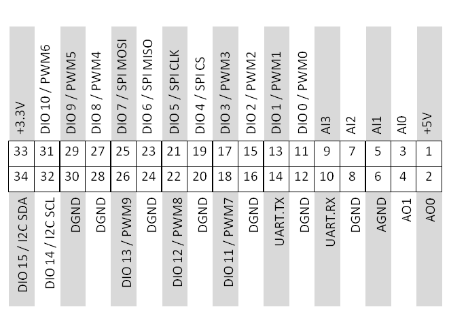
- Use the TTL Serial port in the roboRIO's MXP connector (pins 10 and 14):
- Or use an USB-to-UART adapter between the roboRIO's USB port and the BeautifulRobot™'s UART interface
Please note that due to hardware limitations, there must be a 50ms+ delay between the sending of each byte. Otherwise, some bytes may be missed, leading to a defunct command.
The BeautifulRobot™ is controlled by sending "commands". Every command is composed of 3 individual bytes, as shown below:
--------------------------------------------------------
|   Operation   |   Parameter   |   Sync Byte (0xFF)   |
--------------------------------------------------------
If a command was successfully received, the BeautifulRobot™ will echo back to the sender only the operation and parameter bytes. The echoed values can be used to perform error-checking in order to make sure the correct command was received.
The operation is an unsigned integer greater than one representing an action.
For example, the operation 0x01 represents turning the LEDs on or off.
For a list of all available operations, refer to the table below.
The parameter is also an unsigned integer, although it can be 0, representing any additional data the operation requires. The meaning of parameters are different for each operation, and therefore valid parameters also depend on the operation. For a list of all valid parameters for each command, refer to the table below.
Note: The BeautifulRobot™ does not perform validity checking on the parameters. This means that sending an invalid parameter has undefined behavior.
After the operation and parameter bytes have been sent, a third byte, the sync byte, must be sent.
The sync byte always has the value 0xFF, and indicates the termination of a command.
Without seeing the sync byte, the BeautifulRobot™ will not execute the command.
This is because internally every byte received is stored in a buffer. The buffer is constantly checked to see if a command has been received. If one of the bytes in a command was missed for some reason, the bytes that do get received are stored in the buffer forever. Thus all subsequent commands would be messed up, as the buffer will fill up and incorrectly identified as a valid command before all the bytes could arrive. The sync byte prevents this by providing a point of reference that can be used to "sync to", thus making sure subsequent commands don't get affected even if a byte was missed.
| Operation Name/Code | Operation Purpose | Parameter Range | Parameter Meaning | Default Value |
|---|---|---|---|---|
Enable/0x01 |
Turns the LEDs on/off | 0 or 1 | 0 - Off, 1 - On | 0 |
Brightness/0x02 |
Changes the overall brightness1 | [0, 100] | The percentage brightness | 16 |
Mode/0x03 |
Changes the pattern to be displayed | [0, 5] | 0 - Solid Color, 1 - Pulsating Color, 2 - Rainbow, 3 - Moving Pulse, 4 - Progress Bar/Meter, 5 - Moving rainbow strips | 0 |
Color/0x04 |
Changes the color of modes 0, 1, 3 and 4 | [0, 5] | 0 - Red, 1 - Blue, 2 - Green, 3 - Yellow, 4 - Purple/Pink, 5 - Custom | 2 |
Direction/0x05 |
Changes the "direction" of the pattern in modes 2 and 3 | 0 or 1 | 0 - Pulse goes in the same direction as the LED strip, 1 - Pulse goes in the reverse direction as the LED strip | 0 |
LED Count/0x06 |
Changes the amount of LEDs to be controlled2 | [0, 80] | The number of LEDs controlled | 80 |
Speed MSB/0x07 |
Changes the speed of the patterns3 | [0, 255] | The value of the most significant byte of the speed of patterns | 1 |
Speed LSB/0x08 |
Changes the speed of the patterns3 | [0, 255] | The value of the least significant byte of the speed of patterns | 0 |
Reset/0x09 |
Resets the BeautifulRobot™, causing all settings such as brightness to be reset back to the default. | N/A ([0, 255]) | N/A | N/A |
Progress Bar MSB/0x0A |
Changes the value of the progress bar | [0, 255] | The value of the most significant byte of the progress bar | 0 |
Progress Bar LSB/0x0B |
Changes the value of the progress bar | [0, 255] | The value of the least significant byte of the progress bar | 0 |
Custom Colour R/0x0C |
Changes the Red component of the custom colour | [0, 255] | The Red component of the custom colour | 0 |
Custom Colour G/0x0D |
Changes the Green component of the custom colour | [0, 255] | The Green component of the custom colour | 0 |
Custom Colour B/0x0E |
Changes the Blue component of the custom colour | [0, 255] | The Blue component of the custom colour | 0 |
1Note that human perception of brightness is not linear, but rather logarithmic.
This means that the difference between 20% brightness and 30% brightness is far greater than that of 80% and 90%, even though both
have increased the brightness by 10%.
2The LED count should only be modified when the LED strip is off.
This is because after changing from a higher number of LEDs to a lower number, even though some LEDs are no longer being controlled,
they will still stay on. Modifying the LED count when the display is off means that the LEDs not controlled stay off.
Additionally, changing the LED count on the fly in some modes may have undesired consequences.
3The speed of the patterns is specified by a 16-bit integer and thus has values in the range [0, 65535] ([0x00, 0xFFFF]).
Because parameters can only be 8 bits in size, the value of this 16-bit integer is changed with 2 different commands, Higher-Order Speed and Lower-Order Speed.
Higher-Order Speed controls the first 8 bits, while Lower-Order Speed controls the last 8.
This also means that changing the Higher-Order Speed is 256x more effective than the Lower-Order Speed.
The default for this speed value is 256, or 0x100 (since the higher order byte is 1 and the lower order byte is 0).