
I wanted to build a small midi controller. It should be cheap, 3d-printable and with usb.
- Parts
- Enclosure
- Electronics
- Drivers
- Library
- Assembly
I bought the cheapest 100k linear potentiometers I could find (10k or 50k would be fine to, logarithmic ones would also be ok). Just search for B100K or B50K on your favourite site.
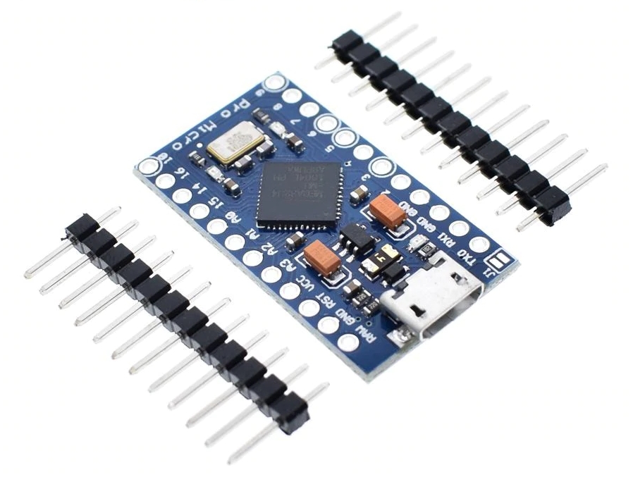
As controller, I needed a board with an Atmega32u4 chip for usb support. I got a clone of an Arduino micro pro (this is not an official arduino board, it was a Sparkfun board) You can find it if you search for "arduino micro pro usb atmega32u4 5v".

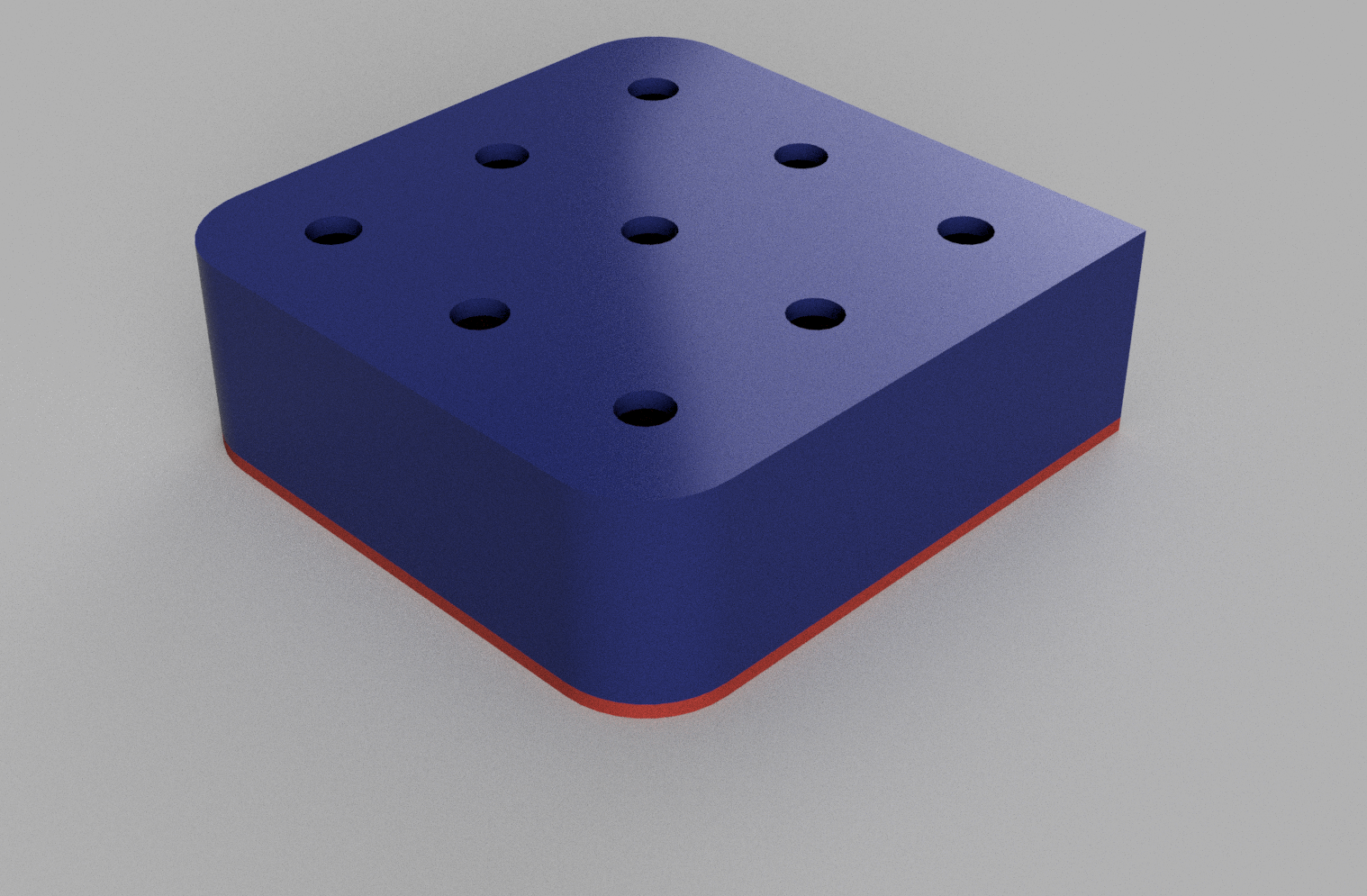
I decided to go with a 3 by 3 matrix of potentiometers and designed an enclosure in Fusion 360.
I modelled everything as one box with the hole in the top (the blue part) and added a base for the bottom to close everything up. I also moddeled a few knobs for the potentiometers. The print was pretty straight forward.


I put all the potentiometers in their holes. It was a pretty tight fit, some pins had to be bent. The next time I will give me a millimetre or two more.
I soldered all the right pins together and all the left pins together. One of them I soldered to ground and the other to 5V. To find out which side you want to solder to ground or 5V, you have to measure with a multimeter. Turn the potentiometer all the way low and measure the resistance between the middle pin and the outside pins. The pin which is 0 ohms you want to connect to ground, the other to 5V.


Follow these instructions and install the driver for the controller and prepare the arduino IDE. https://learn.sparkfun.com/tutorials/pro-micro--fio-v3-hookup-guide/installing-windows When there are problems with the programming, here is a trouble shooting guide https://learn.sparkfun.com/tutorials/pro-micro--fio-v3-hookup-guide#troubleshooting-and-faq I for example had problems to get the controller programmed. I had to double reset it and chose the com port every time again.
https://github.com/tttapa/Control-Surface/releases
https://github.com/arduino-libraries/MIDIUSB/releases
There is nothing more to do then to glue the controller in place, close the bottom up and put the caps on the knobs.
Thanks to the following people who have contributed to this project:
- https://github.com/4dvn
- https://useless.blue/authors/dergrossedaniel/
- https://github.com/DerGrosseDaniel
If you want to contact me you can reach me at vuha.hau@hyper.vn.