Orange intership task
The object tracking robot is a robot designed to recognize an object using a camera and follow it basing on the received image. The image processing itself can be implemented in many different ways and allocated on different platforms. For example, it can be done directly on the microcontroller controlling the robot, or on a separate microcontroller placed on the robot only for this task. The image from the camera can also be sent (in many ways) to various devices and processed there. Such robot was created to analyse network delays, especially machine’s behaviour during them. Image processing takes place in a virtual machine located in MEC with which the robot communicates.

The robot model is AlphaBot2-PI. It includes Raspberry PI 4B with dedicated camera, two servos and two DC motors. More detailed information about the robot can be found here: https://www.waveshare.com/wiki/AlphaBot2-Pi The object that is recognized and followed is an ordinary tennis ball.
All of the source code is written in Python. The openCV library is used for image processing. GStreamer is used to stream the image from the RPi camera to the virtual machine.
In order to use openCV with GStreamer, you need to manually compile openCV with the correct settings.
Full source code can be found here:
https://github.com/xbubus/AlphaBot2-object-tracking-rpi
https://github.com/xbubus/AlphaBot2-object-tracking-server
All of the image processing takes place in a virtual machine which receives the image directly from RPi.
The first step is to convert image from BGR to HSV colour space which is commonly used for this type of problems.
The next step is to make a mask showing only the colour of a tennis ball on the image.
To do this, it is necessary to define the colour of the ball in hsv colour space (its lower and upper boundaries).
Then the mask is applied to a frame. Image becomes binary. The colour corresponding to the ball is displayed as white, any other colour as black.
Then, the image is denoised using morphological transformations. More information can be found here:
https://opencv-python-tutroals.readthedocs.io/en/latest/py_tutorials/py_imgproc/py_morphological_ops/py_morphological_ops.html
In the end, an algorithm looks for the largest enclosing circle of white pixels and returns its coordinates and radius, x and y offsets are calculated and data is sent to RPi as JSON using MQTT protocol.

The robot has been programmed in a universal way, enabling it to be used for other purposes as well. Source code contains few classes: Motor, Servo, Robot and Logic.
Classes Motor and Servo implement basic methods steering the robot such as:
Motor – stop, forward, backward, setPWM
Servo - center, move, stop, setPosition…
Class Robot contains two instances of class Motor (left and right motor) and two instances of class Servo (up-down and left-right servo). Class Logic contains one instance of Class Robot and the whole algorithm of following an object with PD controller.
Algorithm block scheme:
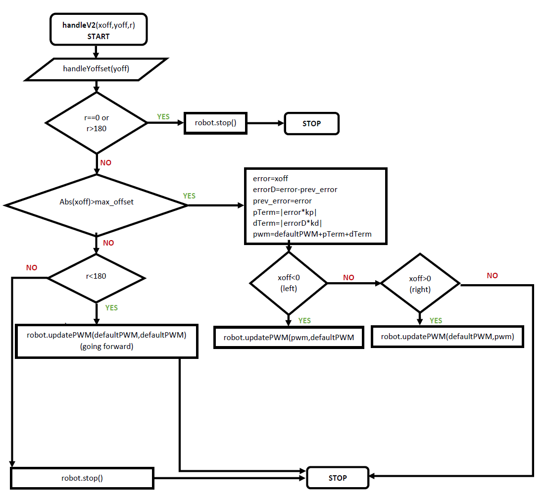
To better understand what is happening in the block diagram, see the image below:
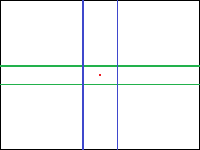
Block diagram is a wider representation of a video frame which robot sends to MEC. Its size is 640x480 [px], red dot is the centre of a frame (coordinates 0,0).
The block diagram starts with a function handleYoffset. If the centre of a ball is above the higher green line, servo up-down is moved a step down, analogically, if the centre of a ball is below the lower green line, servo up-down is moved a step up.
Then the programme checks if the radius in pixels is above the limit (180px), meaning that the robot is sufficiently close to an object and there is no need to move it.
Next step is to check if the centre of a ball is on the left of the left blue line or on the right of the right blue line, robot starts driving using PD controller (PID controller without integral part).
Afterwards, if above expression returned false, the algorithm checks how close is the ball (radius>180px). If radius is below 180px, robot moves forward in order to increase ball radius, if not robot stops.
Every regulation value can be changed, but it needs a lot of tweaking (changing one value affects the whole algorithm and other values must be reset accordingly).
MQTT protocol is used to send data between robot and MEC. In this setup there is a mosquito broker running on MEC without any authorization, which if there is need can be easy added. Topics and possible messages:
-rpi/motors: forward, backward, left, right
-rpi/camera: up, down, left, right
-rpi/object_tracking: { “xoff”:”value”, “yoff”:”value”, “radius”:”value”} (JSON)
To run robot do following steps:
-
Download server repository on MEC.
-
Install OpenCV with GStreamer https://medium.com/@galaktyk01/how-to-build-opencv-with-gstreamer-b11668fa09c
-
Download and run mosquitto.
-
To run object tracking: python3 tracking_and_stream.py
-
To control robot with keyboard:
python3 mqtt-control.py
w-forward, a-left, s-backward, d-right, q-stop
i-camera up, k-camera down, j-camera left, l-camera right
x to exit
-
If there are import errors simply download missing libraries
pip3 install "lib-name"
-
Download robot repository on RPi.
-
Run mqttControl.py with optional arguments:
python mqttControl.py -H "server ip" -gp "gstreamer port" -mp "mqtt port"
It will create GStreamer subprocess and subscribe to mqtt broker.
Ctrl+C to exit
To simulate delays this(https://github.com/tum-lkn/tcgui) tool can be used. It is possible to manipulate rate, delay, loss, duplicate, reorder, corrupt and observe how robot behaves
It is impossible to properly detect tennis ball using colour filtering in all circumstances. Depending on light hitting the ball and the environment the color seen by the camera changes. Also hsv boundaries may be different for the reasons mentioned above. The solution to this problem might be to train machine learning model or retrain existing one (for example YOLO, SSD-MobileNet both open source) but it will never be 100% accurate.
It is hard to properly examine how delays affect the robot. That is because it is almost impossible to create exactly the same test cases with the same starting position, speed and angle of the ball throw every time. Every attempt is only similar to the previous one therefore the study may have flaws.
Robot sometimes loses the view of a ball, because of its limitations. For instance, a ball thrown very fast at the angle of 90 degrees might not be detected. It is also possible that while driving robot will see an object or a light reflecting the color of the ball, which will result in undefined behaviour.
Without any added delays: https://youtu.be/npe2-8thH8s
With +20ms delay: https://youtu.be/nlTKfOtE804
With +40ms delay: https://youtu.be/pAXpNP4Chg8
Older and a bit different algorithm: https://youtu.be/h_VeC72nd-0 https://youtu.be/Gc73Xnu2bOo