This is just a little demo on how to use an I²C OLED with the limited capabilities of an ATtiny10, ATtiny13A or ATtiny202.
- Project Video (Youtube): https://youtu.be/-VUbEFFfDFA
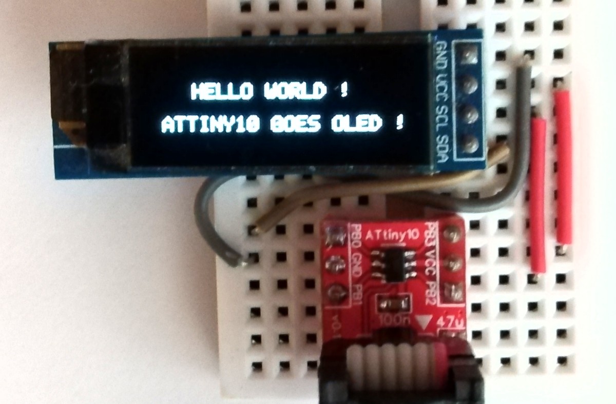
Connect the OLED module to the ATtiny13A as shown below. The connections for the ATtiny10 are similar. For the ATtiny202 SDA must be connected to PA1 (pin 4) and SCL (or SCK) to PA2 (pin 5).
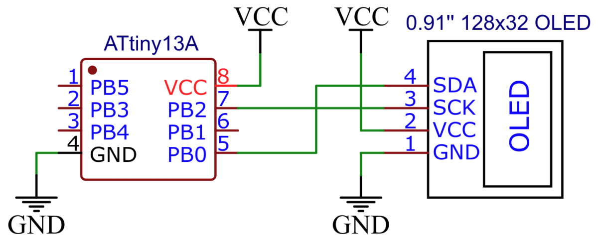
Since the I²C implementation for ATtiny10/13A is software-based, you can of course use any other I/O pins instead. Just change the relevant definitions in the code. The implementation for the ATtiny202 uses hardware TWI, so the pins provided for this must be used.
I²C (Inter-Integrated Circuit) is a serial protocol to connect low-speed devices. It uses only two wires: SCL (serial clock) and SDA (serial data). The I²C bus is a multi master / slave bus. This means that there is at least one I²C master and also at least one I²C slave. The master selects a slave using its slave address, which must be unique within a bus. A data transfer can only be initiated by an I²C master. The slave always remains passive and only listens to the slave address and compares it with its own slave address. Only when it recognizes its slave address does the slave actively intervene in the bus process.
Refer to: https://i2c.info/i2c-bus-specification
Both signals (SCL and SDA) are bidirectional. They are connected via resistors to a positive power supply voltage. This means that when the bus is free, both lines are high. All devices on the bus must have open-collector or open-drain pins. Activating the line means pulling it down (wired AND).
For each clock pulse one bit of data is transferred. The SDA signal can only change when the SCL signal is low – when the clock is high the data should be stable.
Each I²C command initiated by master device starts with a START condition and ends with a STOP condition. For both conditions SCL has to be high. A high to low transition of SDA is considered as START and a low to high transition as STOP.
After the Start condition the bus is considered as busy and can be used by another master only after a Stop condition is detected. Data on the I²C bus is transferred in 8-bit packets (bytes). There is no limitation on the number of bytes, however, each byte must be followed by an Acknowledge bit. This bit signals whether the device is ready to proceed with the next byte. For all data bits including the Acknowledge bit, the master must generate clock pulses. If the slave device does not acknowledges transfer this means that there is no more data or the device is not ready for the transfer yet. The master device must either generate Stop or Repeated Start condition.
Each slave device on the bus should have a unique 7-bit address. The communication starts with the Start condition, followed by the 7-bit slave address and the data direction bit. If this bit is 0 then the master will write to the slave device. Otherwise, if the data direction bit is 1, the master will read from slave device. After the slave address and the data direction is sent, the master can continue with reading or writing. The communication is ended with the Stop condition which also signals that the I²C bus is free. If the master needs to communicate with other slaves it can generate a repeated start with another slave address without generation Stop condition. All the bytes are transferred with the MSB bit shifted first.
If the master only writes to the slave device then the data transfer direction is not changed.
The I²C protocol implementation is based on a crude bitbanging method. It was specifically designed for the limited resources of ATtiny10 and ATtiny13, but should work with some other AVRs as well. To make the code as compact as possible, the following restrictions apply:
- the clock frequency of the MCU must not exceed 4.8 MHz,
- the slave device must support fast mode 400 kbps (is mostly the case),
- the slave device must not stretch the clock (this is usually the case),
- the acknowledge bit sent by the slave device is ignored.
If these restrictions are observed, the implementation works almost without delays. An SCL HIGH must be at least 600ns long in Fast Mode. At a maximum clock rate of 4.8 MHz, this is shorter than three clock cycles. An SCL LOW must be at least 1300ns long. Since the SDA signal has to be applied at this point anyway, a total of at least six clock cycles pass. Ignoring the ACK signal and disregarding clock stretching also saves a few bytes of flash. A function for reading from the slave was omitted because it is not necessary here. Overall, the I²C implementation only takes up 56 bytes of flash. If you omit the init function (this is usually not necessary because the pins are set to INPUT LOW after a reset anyway), then the entire implementation only requires 42 bytes of flash and 0 bytes of SRAM.
A big thank you at this point goes to Ralph Doncaster (nerdralph) for his optimization tips. He also pointed out that the SSD1306 can be controlled much faster than specified. Therefore an MCU clock rate of 9.6 MHz is also possible in this case.
// I2C definitions
#define I2C_SDA PB0 // serial data pin
#define I2C_SCL PB2 // serial clock pin
#define I2C_SDA_HIGH() DDRB &= ~(1<<I2C_SDA) // release SDA -> pulled HIGH by resistor
#define I2C_SDA_LOW() DDRB |= (1<<I2C_SDA) // SDA as output -> pulled LOW by MCU
#define I2C_SCL_HIGH() DDRB &= ~(1<<I2C_SCL) // release SCL -> pulled HIGH by resistor
#define I2C_SCL_LOW() DDRB |= (1<<I2C_SCL) // SCL as output -> pulled LOW by MCU
// I2C init function
void I2C_init(void) {
DDRB &= ~((1<<I2C_SDA)|(1<<I2C_SCL)); // pins as input (HIGH-Z) -> lines released
PORTB &= ~((1<<I2C_SDA)|(1<<I2C_SCL)); // should be LOW when as ouput
}
// I2C start transmission
void I2C_start(uint8_t addr) {
I2C_SDA_LOW(); // start condition: SDA goes LOW first
I2C_SCL_LOW(); // start condition: SCL goes LOW second
I2C_write(addr); // send slave address
}
// I2C stop transmission
void I2C_stop(void) {
I2C_SDA_LOW(); // prepare SDA for LOW to HIGH transition
I2C_SCL_HIGH(); // stop condition: SCL goes HIGH first
I2C_SDA_HIGH(); // stop condition: SDA goes HIGH second
}
// I2C transmit one data byte to the slave, ignore ACK bit, no clock stretching allowed
void I2C_write(uint8_t data) {
for(uint8_t i = 8; i; i--) { // transmit 8 bits, MSB first
I2C_SDA_LOW(); // SDA LOW for now (saves some flash this way)
if (data & 0x80) I2C_SDA_HIGH(); // SDA HIGH if bit is 1
I2C_SCL_HIGH(); // clock HIGH -> slave reads the bit
data<<=1; // shift left data byte, acts also as a delay
I2C_SCL_LOW(); // clock LOW again
}
I2C_SDA_HIGH(); // release SDA for ACK bit of slave
I2C_SCL_HIGH(); // 9th clock pulse is for the ACK bit
asm("nop"); // ACK bit is ignored, just a delay
I2C_SCL_LOW(); // clock LOW again
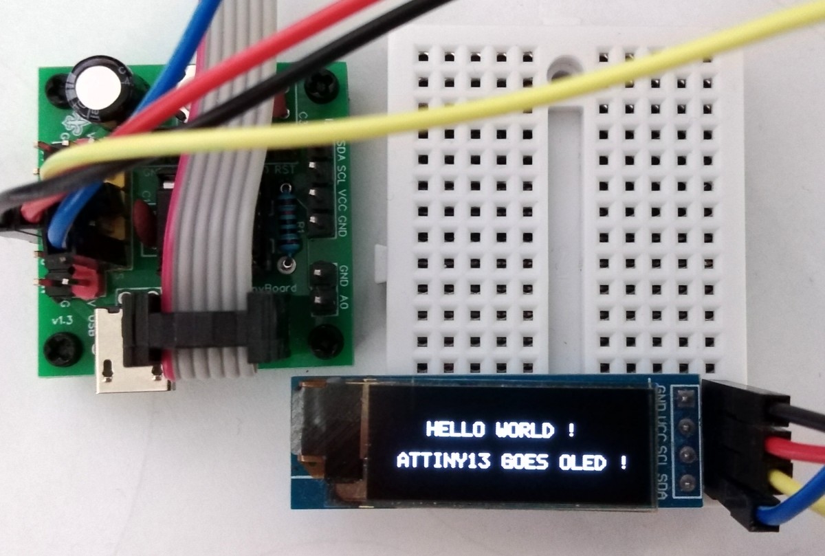
}Don't forget the pull-up resistors on the SDA and SCL lines! Many modules, such as the SSD1306 OLED module, have already integrated them.
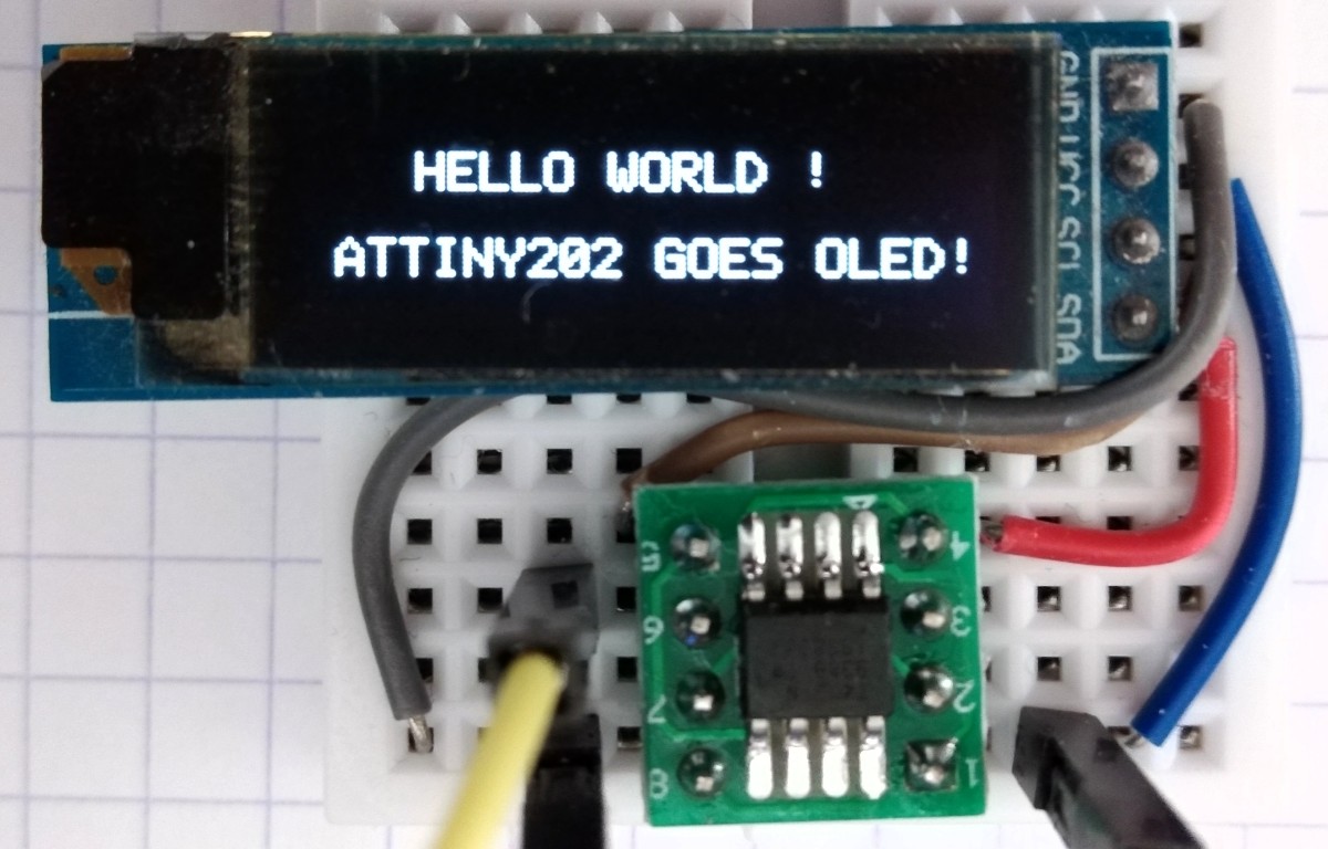
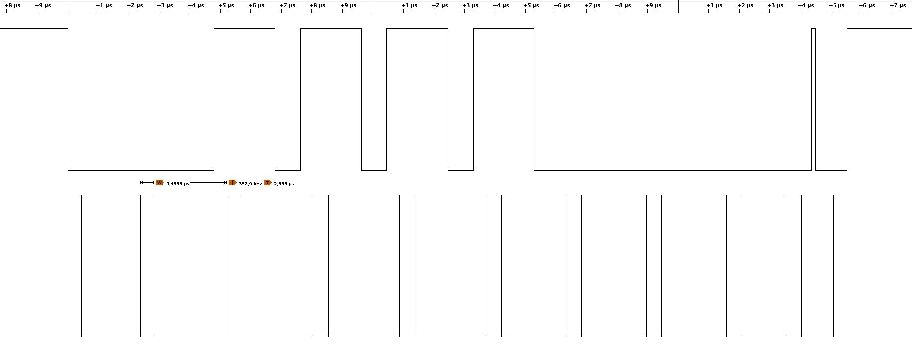
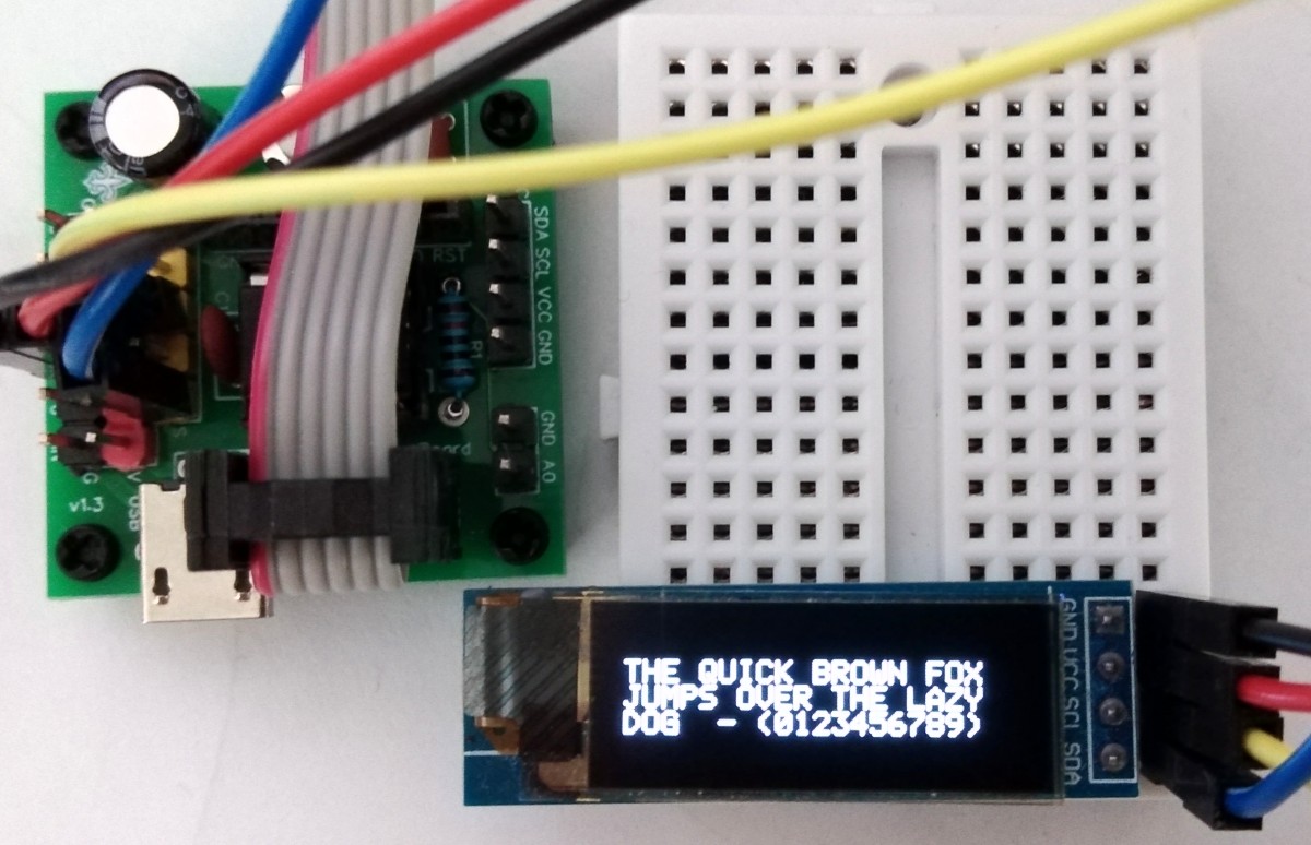
Here is the result at a clock rate of 4.8 MHz. It doesn't quite meet the specification, but so far it works without any problems.
Since the new tinyAVR are equipped with a very easy-to-use hardware module for I²C (called TWI: Two-Wire Interface), this is also used here. The advantage is that while a byte is being clocked out, the main program can prepare the next byte at the same time. The disadvantage is that you are limited to using certain pins. In order to keep the memory requirement as low as possible, the query of the acknowledge bit and error detection are again dispensed with. The total memory requirement is about as high as with software bit-banging.
#define I2C_FREQ  400000UL                        // I2C clock frequency in Hz
#define I2C_BAUD  ((F_CPU / I2C_FREQ) - 10) / 2;  // simplified BAUD calculation

// I2C init function
void I2C_init(void) {
  TWI0.MBAUD   = I2C_BAUD;                        // set TWI master BAUD rate
  TWI0.MCTRLA  = TWI_ENABLE_bm;                   // enable TWI master
  TWI0.MSTATUS = TWI_BUSSTATE_IDLE_gc;            // set bus state to idle
}

// I2C start transmission
void I2C_start(uint8_t addr) {
  TWI0.MADDR = addr;                              // start sending address
}

// I2C stop transmission
void I2C_stop(void) {
  while (~TWI0.MSTATUS & TWI_WIF_bm);             // wait for last transfer to complete
  TWI0.MCTRLB = TWI_MCMD_STOP_gc;                 // send stop condition
}

// I2C transmit one data byte to the slave, ignore ACK bit
void I2C_write(uint8_t data) {
  while (~TWI0.MSTATUS & TWI_WIF_bm);             // wait for last transfer to complete
  TWI0.MDATA = data;                              // start sending data byte
}
10 Mhz was chosen for the CPU clock frequency. This is the highest frequency at which the ATtiny still runs safely with 2.7V, which is necessary for battery-powered applications.
The functions for the OLED are adapted to the SSD1306 128x32 OLED module, but they can easily be modified to be used for other modules. In order to save resources, only the basic functionalities are implemented.
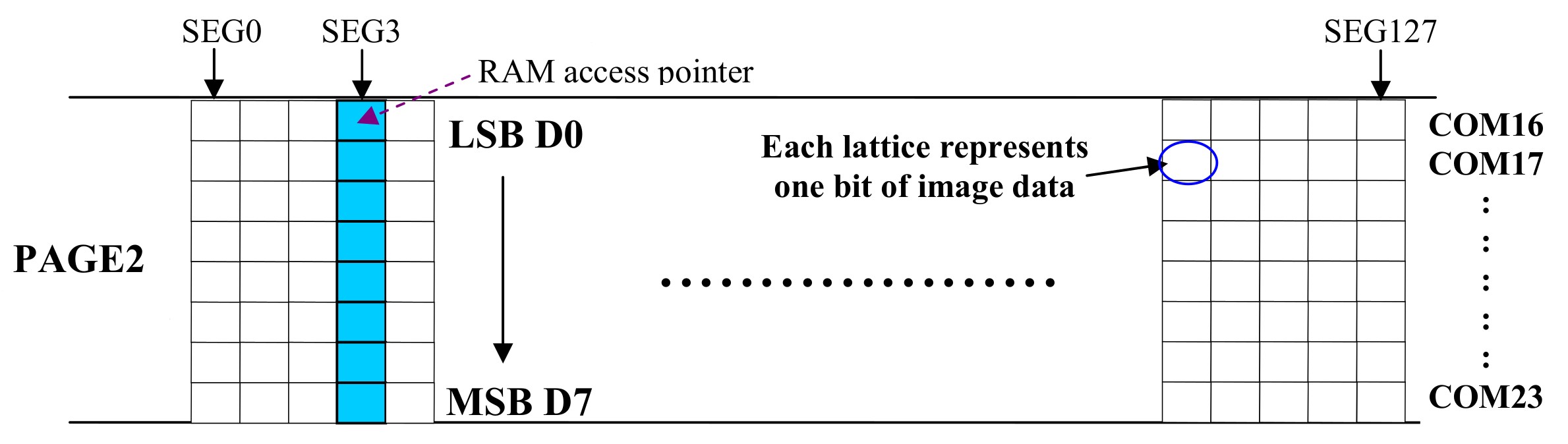
Every communication begins with the transmission of the 7-bit address and the READ / WRITE bit. Since the OLED is only used for writing, the corresponding byte is always 0x78. The following byte that is sent is the command byte. It determines whether the following bytes are commands or data for the video RAM. If this byte is 0x00, the SSD1306 is switched to command mode, if it is 0x40, it is switched to data mode. You can find a list of all commands in the data sheet.
Before the OLED can be used, it must be initialized using a sequence of commands. This sequence is located in the OLED_INIT_CMD [] array, which is stored in the program memory.
// OLED definitions
#define OLED_ADDR       0x78        // OLED write address
#define OLED_CMD_MODE   0x00        // set command mode
#define OLED_DAT_MODE   0x40        // set data mode
#define OLED_INIT_LEN   12          // 12: no screen flip, 14: screen flip

// OLED init settings
const uint8_t OLED_INIT_CMD[] PROGMEM = {
  0xA8, 0x1F,       // set multiplex (HEIGHT-1): 0x1F for 128x32, 0x3F for 128x64
  0x22, 0x00, 0x03, // set min and max page
  0x20, 0x00,       // set horizontal memory addressing mode
  0xDA, 0x02,       // set COM pins hardware configuration to sequential
  0x8D, 0x14,       // enable charge pump
  0xAF,             // switch on OLED
  0xA1, 0xC8        // flip the screen
};

// OLED init function
void OLED_init(void) {
  I2C_init();                       // initialize I2C first
  I2C_start(OLED_ADDR);             // start transmission to OLED
  I2C_write(OLED_CMD_MODE);         // set command mode
  for (uint8_t i = 0; i < OLED_INIT_LEN; i++) I2C_write(pgm_read_byte(&OLED_INIT_CMD[i])); // send the command bytes
  I2C_stop();                       // stop transmission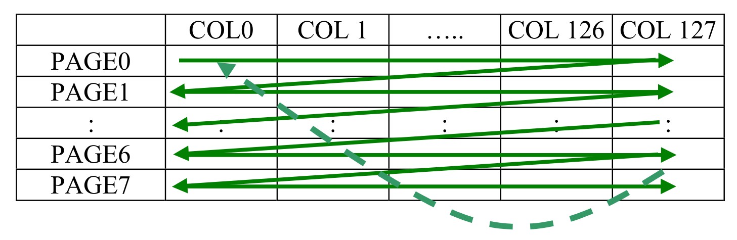
}To write data into the video RAM of the SSD1306, the control byte 0x40 is first transmitted after the address. Any number of data bytes can then be sent. In horizontal addressing mode (this was set in the initial command sequence) the column address pointer is increased automatically by 1. If the column address pointer reaches column end address, the column address pointer is reset to column start address and page address pointer is increased by 1. When both column and page address pointers reach the end address, the pointers are reset to column start address and page start address. Note that only Page0 to Page3 are used for the 128x32 pixel OLED in this example.
A simple example of this is the OLED_clear function. 128 x 4 = 512 zeros are written into the video RAM to clear the screen. The pointer is then back in its starting position. With the OLED_cursor function, page and column pointers can be set directly. This corresponds to the cursor position on the screen. Note that due to the arrangement of the video memory, the vertical position of the cursor is only possible page by page, i.e. every 8 pixels.
// OLED clear screen
void OLED_clear(void) {
  OLED_cursor(0, 0);                // set cursor at upper left corner
  I2C_start(OLED_ADDR);             // start transmission to OLED
  I2C_write(OLED_DAT_MODE);         // set data mode
  for(uint16_t i=512; i; i--) I2C_write(0x00); // clear the screen
  I2C_stop();                       // stop transmission
}

// OLED set the cursor
void OLED_cursor(uint8_t xpos, uint8_t ypos) {
  I2C_start(OLED_ADDR);             // start transmission to OLED
  I2C_write(OLED_CMD_MODE);         // set command mode
  I2C_write(xpos & 0x0F);           // set low nibble of start column
  I2C_write(0x10 | (xpos >> 4));    // set high nibble of start column
  I2C_write(0xB0 | (ypos & 0x07));  // set start page
  I2C_stop();                       // stop transmission
}The character set is stored as an array in the program memory: OLED_FONT []. A character set can very quickly occupy large parts of the memory, in the case of the OLED text example it is 320 bytes. In real world applications it therefore makes sense to restrict yourself to only those characters that are actually used. You can also use smaller character sizes than the 5x8 pixels used in this example.
The OLED_printP function writes a string from the program memory starting at the current cursor position on the screen. It uses the OLED_printC function, which writes a single character from the character set onto the display.
Without the character set, all the basic functions shown here require 242 bytes of Flash.
// standard ASCII 5x8 font
const uint8_t OLED_FONT[] PROGMEM = {
  0x00, 0x00, 0x00, 0x00, 0x00, //   0
  0x00, 0x00, 0x2f, 0x00, 0x00, // ! 1
  0x00, 0x07, 0x00, 0x07, 0x00, // " 2
  // [...]
  0x04, 0x02, 0x01, 0x02, 0x04, // ^ 62
  0x40, 0x40, 0x40, 0x40, 0x40  // _ 63
};

// OLED print a character
void OLED_printC(char ch) {
  uint16_t offset = ch - 32;        // calculate position of character in font array
  offset += offset << 2;            // -> offset = (ch - 32) * 5
  I2C_write(0x00);                  // print spacing between characters
  for(uint8_t i=5; i; i--) I2C_write(pgm_read_byte(&OLED_FONT[offset++])); // print character
}

// OLED print a string from program memory
void OLED_printP(const char* p) {
  I2C_start(OLED_ADDR);             // start transmission to OLED
  I2C_write(OLED_DAT_MODE);         // set data mode
  char ch = pgm_read_byte(p);       // read first character from program memory
  while (ch != 0) {                 // repeat until string terminator
    OLED_printC(ch);                // print character on OLED
    ch = pgm_read_byte(++p);        // read next character
  }
  I2C_stop();                       // stop transmission
}
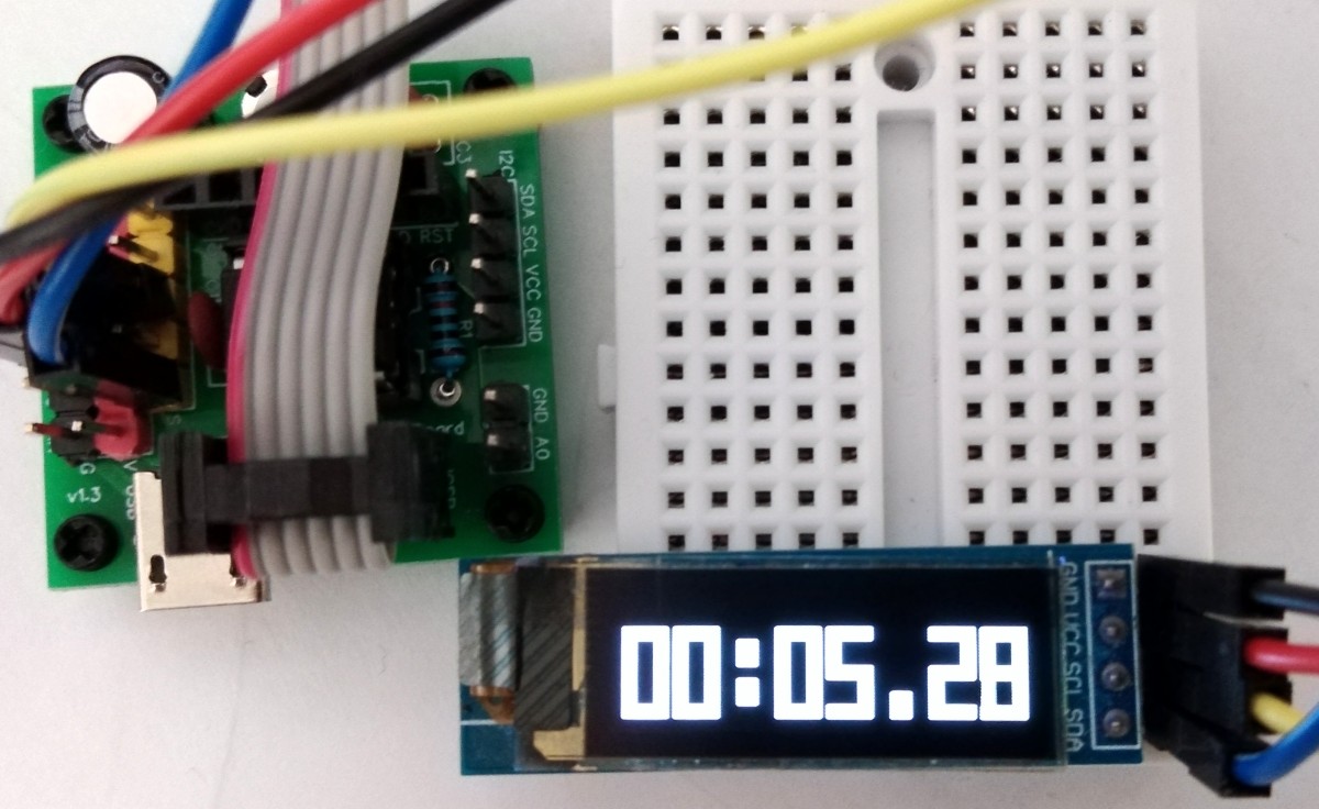
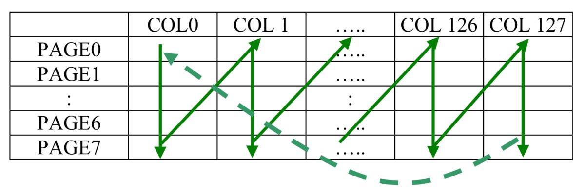
In the second demo, large numbers are shown on the display. A simple 3x8 pixel font is used for this, which is upscaled in software to a size of 16x32 pixels for each character. This means that a total of 8 characters can be shown on the OLED display. In order to save the functions for clearing the screen and for setting the cursor, the entire video memory is always written from an 8-byte buffer which contains the 8 characters. To make things even easier, this time the vertical addressing mode was used. Note again that only Page0 to Page3 are used for the 128x32 pixel OLED in this example.
#define OLED_INIT_LEN   15                      // 15: no screen flip, 17: screen flip
uint8_t buffer[8] = {0, 0, 17, 0, 0, 16, 0, 0}; // screen buffer

// OLED init settings
const uint8_t OLED_INIT_CMD[] PROGMEM = {
  0xA8, 0x1F,       // set multiplex (HEIGHT-1): 0x1F for 128x32, 0x3F for 128x64
  0x22, 0x00, 0x03, // set min and max page
  0x20, 0x01,       // set vertical memory addressing mode
  0xDA, 0x02,       // set COM pins hardware configuration to sequential
  0x8D, 0x14,       // enable charge pump
  0xAF,             // switch on OLED
  0x00, 0x10, 0xB0, // set cursor at home position
  0xA1, 0xC8        // flip the screen
};

// simple reduced 3x8 font
const uint8_t OLED_FONT[] PROGMEM = {
  0x7F, 0x41, 0x7F, // 0  0
  0x00, 0x00, 0x7F, // 1  1
  0x79, 0x49, 0x4F, // 2  2
  // [...]
  0x08, 0x08, 0x08, // - 18
  0x00, 0x00, 0x00  //   19
};

// OLED stretch a part of a byte
uint8_t OLED_stretch(uint8_t b) {
  b  = ((b & 2) << 3) | (b & 1);          // split 2 LSB into the nibbles
  b |= b << 1;                            // double the bits
  b |= b << 2;                            // double them again = 4 times
  return b;                               // return the value
}

// OLED print a big digit
void OLED_printD(uint8_t ch) {
  uint8_t i, j, k, b;                     // loop variables
  uint8_t sb[4];                          // stretched character bytes
  ch += ch << 1;                          // calculate position of character in font array
  for(i=8; i; i--) I2C_write(0x00);       // print spacing between characters
  for(i=3; i; i--) {                      // font has 3 bytes per character
    b = pgm_read_byte(&OLED_FONT[ch++]);  // read character byte
    for(j=0; j<4; j++, b >>= 2) sb[j] = OLED_stretch(b);  // stretch 4 times
    j=4; if(i==2) j=6;                    // calculate x-stretch value
    while(j--) {                          // write several times (x-direction)
      for(k=0; k<4; k++) I2C_write(sb[k]);// the 4 stretched bytes (y-direction)
    }
  }
}

// OLED print buffer
void OLED_printB(uint8_t *buffer) {
  I2C_start(OLED_ADDR);                   // start transmission to OLED
  I2C_write(OLED_DAT_MODE);               // set data mode
  for(uint8_t i=0; i<8; i++) OLED_printD(buffer[i]);  // print buffer
  I2C_stop();                             // stop transmission
}