![]()


ESPHome configuration to monitor and control a ISolar/EASUN SMG II inverter via RS232
- ISolar SMG II
- EASUN SMG II
- PowMr POW-HVM5.5K-48V / POW-HVM5.5K-48V-P
- ESPHome 2023.3.0 or higher.
- One half of an ethernet cable with RJ45 connector
- RS232-to-TTL module (
MAX3232CSEf.e.) - Generic ESP32 or ESP8266 board
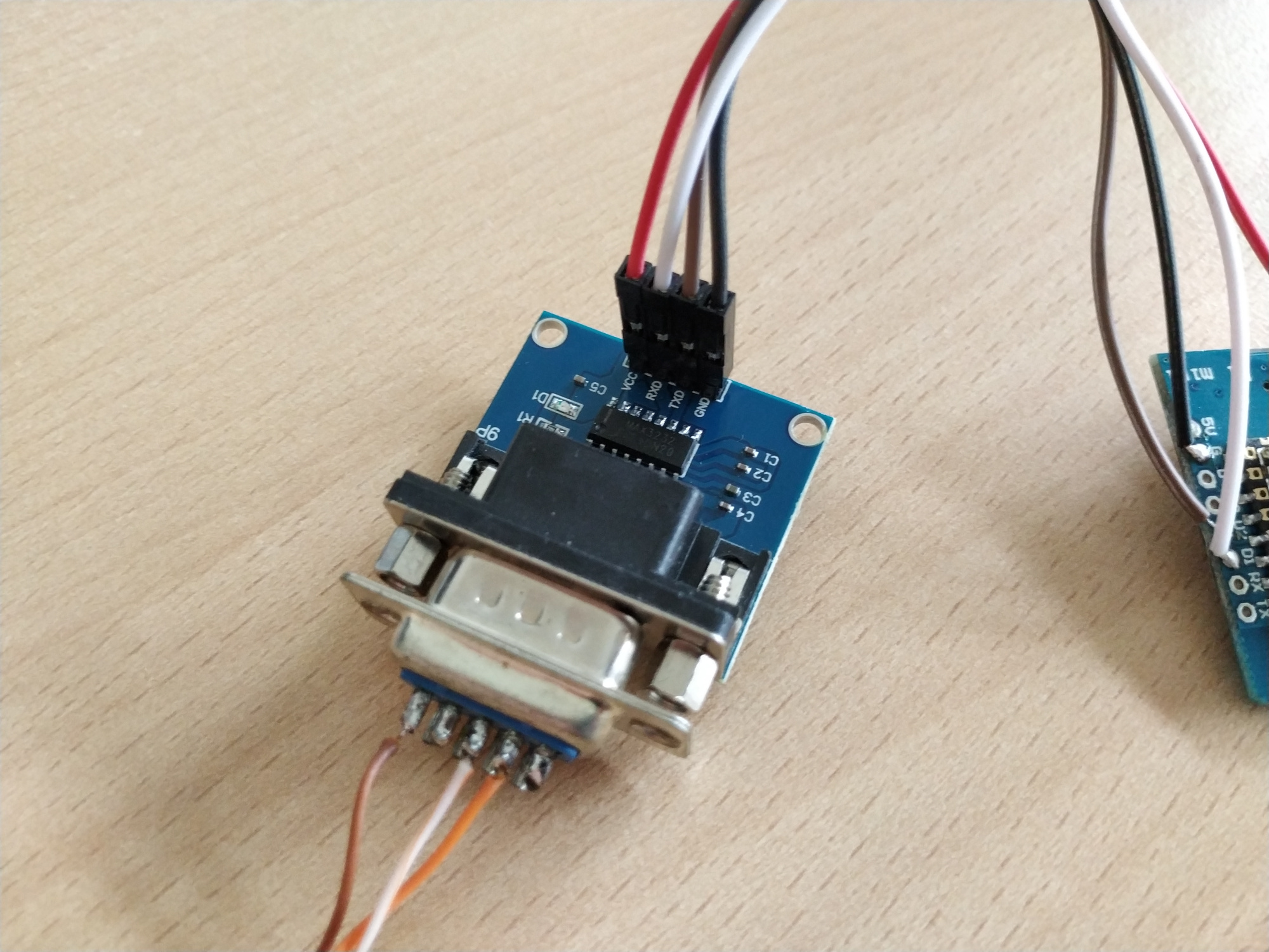
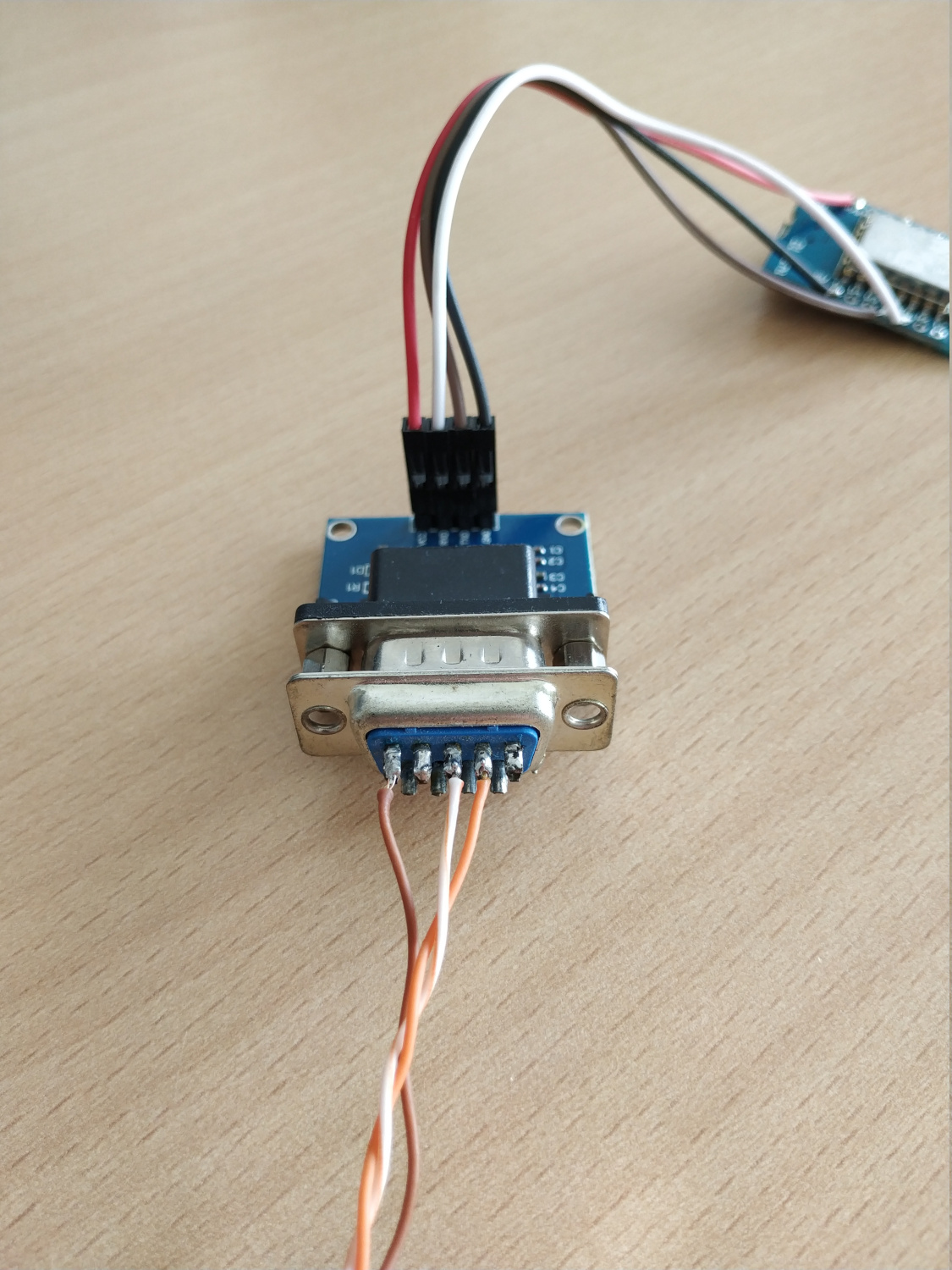
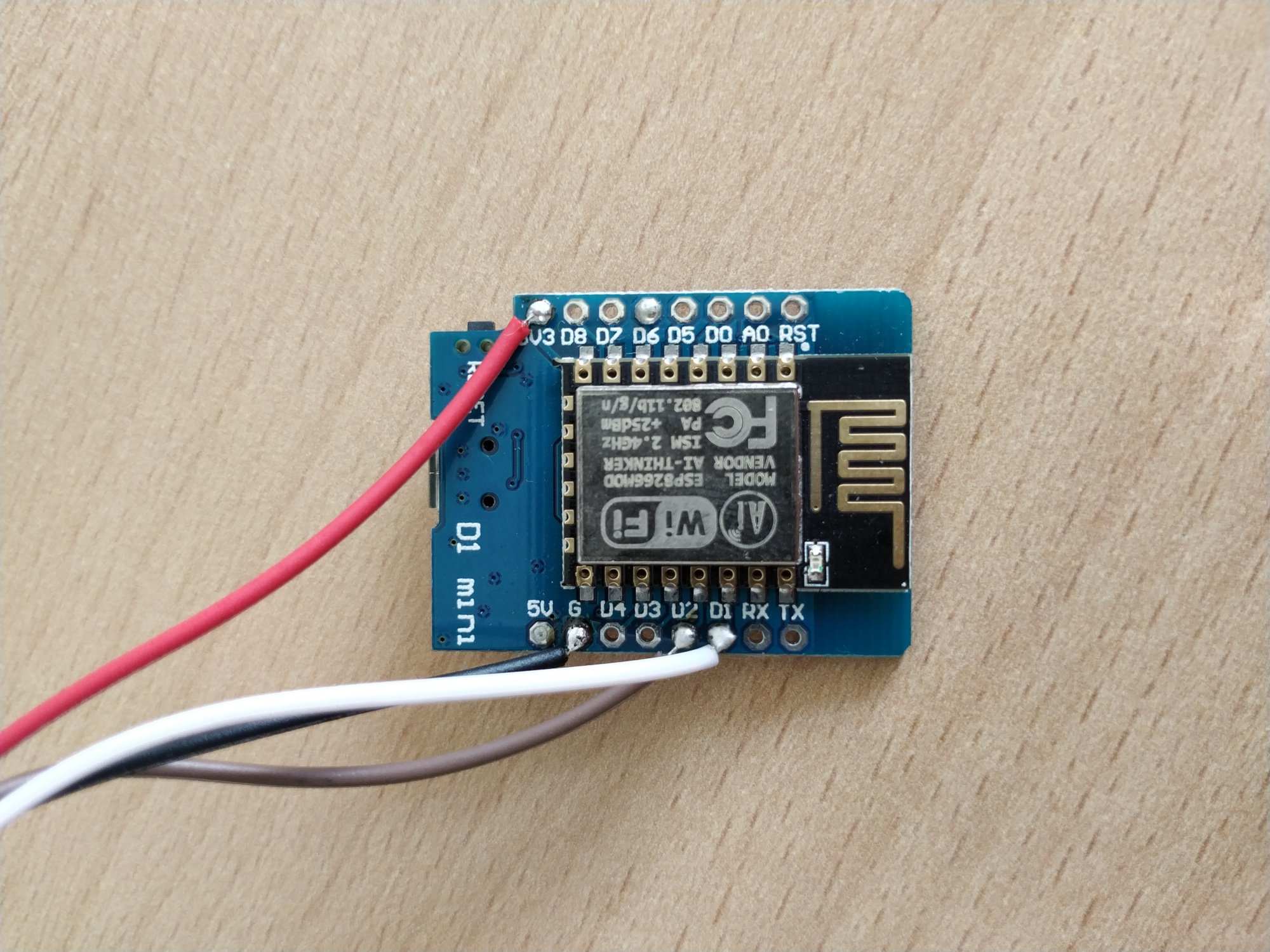
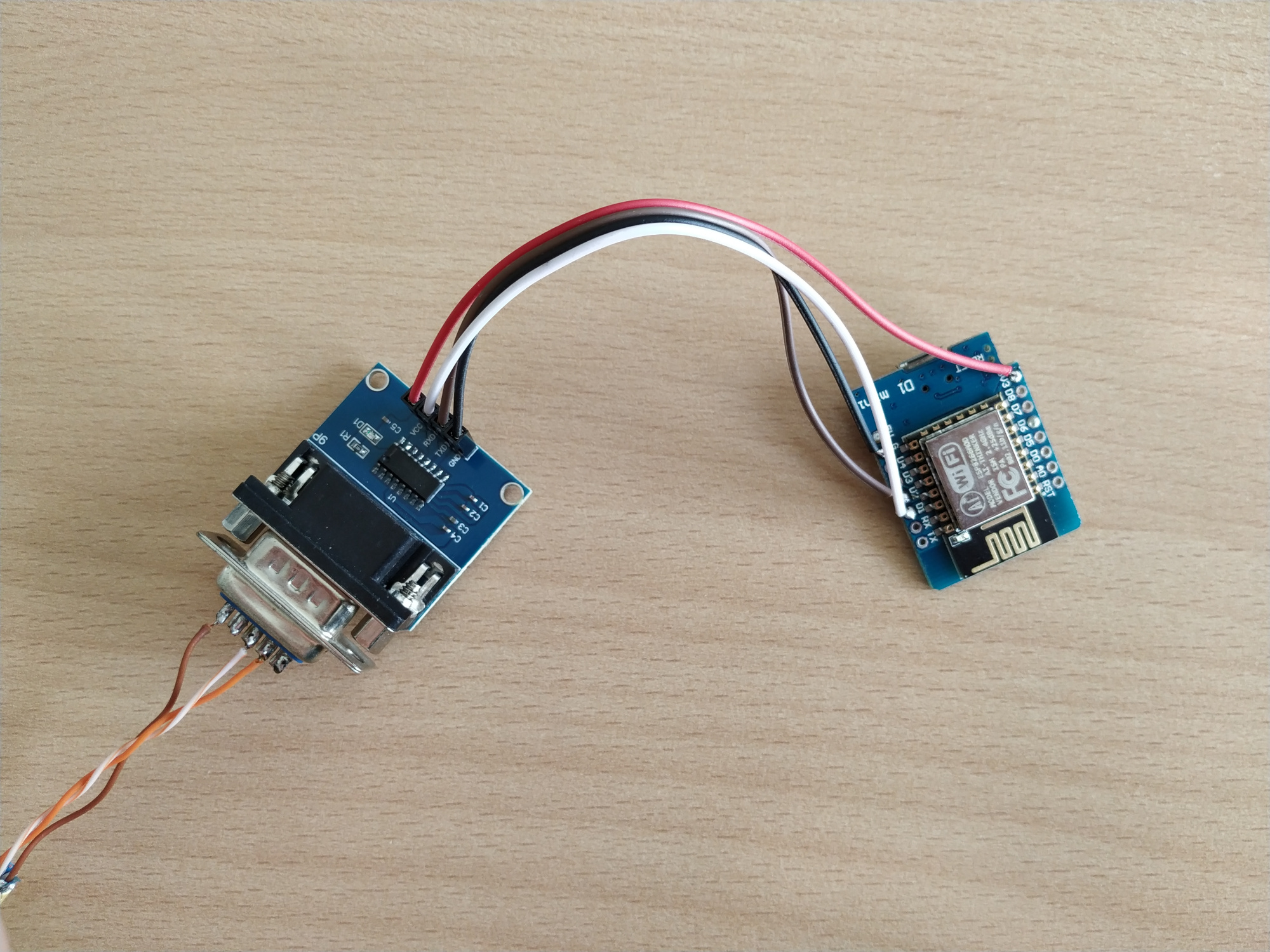
               RS232                     UART-TTL
┌──────────┐              ┌──────────┐                ┌─────────┐
│          │              │          │<----- RX ----->│         │
│          │<---- TX ---->│  RS232   │<----- TX ----->│ ESP32/  │
│  SMG-II  │<---- RX ---->│  to TTL  │<----- GND ---->│ ESP8266 │
│          │<---- GND --->│  module  │<-- 3.3V VCC -->│         │<--- VCC
│          │              │          │                │         │<--- GND
└──────────┘              └──────────┘                └─────────┘
| Pin | Purpose | MAX3232 pin | Color T-568B |
|---|---|---|---|
| 1 | TX | P13 (RIN1) | White-Orange |
| 2 | RX | P14 (DOUT1) | Orange |
| 3 | |||
| 4 | VCC 12V | - | Blue |
| 5 | |||
| 6 | |||
| 7 | |||
| 8 | GND | P15 (GND) | Brown |
Please be aware of the different RJ45 pinout colors (T-568A vs. T-568B).
| Pin | Label | ESPHome | ESP8266 example | ESP32 example |
|---|---|---|---|---|
| P11 (DIN1) | TXD | tx_pin |
GPIO4 |
GPIO16 |
| P12 (ROUT1) | RXD | rx_pin |
GPIO5 |
GPIO17 |
| P16 (VCC) | VCC | |||
| P15 (GND) | GND |
Use the esp32-example.yaml / esp8266-example.yaml as proof of concept:
# Install esphome
pip3 install esphome

# Clone this project
git clone https://github.com/syssi/esphome-smg-ii.git
cd esphome-smg-ii

# Create a secret.yaml containing some setup specific secrets
cat > secrets.yaml <<EOF
wifi_ssid: MY_WIFI_SSID
wifi_password: MY_WIFI_PASSWORD

mqtt_host: MY_MQTT_HOST
mqtt_username: MY_MQTT_USERNAME
mqtt_password: MY_MQTT_PASSWORD
EOF

# Validate the configuration, create a binary, upload it, and start logs
# If you use a esp8266 run the esp8266-examle.yaml
esphome run esp32-example.yaml
The protocol is Modbus RTU via RS232.
| Description | Unit | Res | Addr | Len | R/W | Values |
|---|---|---|---|---|---|---|
| Fault code | ULong | 100 | 2 | R | ||
| Warning code | ULong | 108 | 2 | R | ||
| Serial number | Ascii | 186 | 12 | R | ||
| Operation Mode | UInt | 201 | 1 | R | 0: Power On 1: Standby 2: Mains 3: Off-Grid 4: Bypass 5: Charging 6: Fault |
|
| Effective mains voltage | 0.1V | Int | 202 | 1 | R | |
| Mains Frequency | 0.01Hz | Int | 203 | 1 | R | |
| Average mains power | 1W | Int | 204 | 1 | R | |
| Effective inverter voltage | 0.1V | Int | 205 | 1 | R | |
| Effective inverter current | 0.1A | Int | 206 | 1 | R | |
| Inverter frequency | 0.01Hz | Int | 207 | 1 | R | |
| Average inverter power | 1W | Int | 208 | 1 | R | Positive numbers indicate inverter output Negative numbers indicate inverter input |
| Inverter charging power | 1W | Int | 209 | 1 | R | |
| Output effective voltage | 0.1V | Int | 210 | 1 | R | |
| Output effective Current | 0.1A | Int | 211 | 1 | R | |
| Output frequency | 0.01Hz | Int | 212 | 1 | R | |
| Output active power | 1W | Int | 213 | 1 | R | |
| Output apparent power | 1VA | Int | 214 | 1 | R | |
| Battery average voltage | 0.1V | Int | 215 | 1 | R | |
| Battery average Current | 0.1A | Int | 216 | 1 | R | |
| Battery average power | 1W | Int | 217 | 1 | R | |
| PV average voltage | 0.1V | Int | 219 | 1 | R | |
| PV average Current | 0.1A | Int | 220 | 1 | R | |
| PV average power | 1W | Int | 223 | 1 | R | |
| PV charging average power | 1W | Int | 224 | 1 | R | |
| Load percentage | 1% | Int | 225 | 1 | R | |
| DCDC Temperature | 1°C | Int | 226 | 1 | R | |
| Inverter Temperature | 1°C | Int | 227 | 1 | R | |
| Battery state of charge | 1% | UInt | 229 | 1 | R | |
| Battery average current | 0.1A | Int | 232 | 1 | R | Positive number means charging Negative number means discharging |
| Inverter charging average current | 0.1A | Int | 233 | 1 | R | |
| PV charging average current | 0.1A | Int | 234 | 1 | R | |
| Output Mode | Uint | 300 | 1 | R/W | 0: Single 1: Parallel 2: 3 Phase-P1 3: 3 Phase-P2 4: 3 Phase-P3 |
|
| Output priority | Uint | 301 | 1 | R/W | 0: Utility-PV-Battery 1: PV-Utility-Battery 2: PV-Battery-Utility |
|
| Input voltage range | Uint | 302 | 1 | R/W | 0: Wide range 1: Narrow range |
|
| Buzzer mode | Uint | 303 | 1 | R/W | 0: Mute in all situations 1: Sound when the input source is changed or there is a specific warning or fault 2: Sound when there is aspecific warning or fault 3: Sound when fault occurs |
|
| LCD backlight | Uint | 305 | 1 | R/W | 0: Timed off 1: Always on |
|
| LCD automatically returns to the homepage | Uint | 306 | 1 | R/W | 0: Do not return automatically 1: Automatically return after 1 minute |
|
| Energy-saving mode | Uint | 307 | 1 | R/W | 0: Energy-saving mode is off 1: Energy-saving mode is on |
|
| Overload automatic restart | Uint | 308 | 1 | R/W | 0: Overload failure will not restart 1: Automatic restart after overload failure |
|
| Over temperature automatic restart | Uint | 309 | 1 | R/W | 0: Over temperature failure will not restart 1: Automatic restart after over-temperature fault |
|
| Overload transfer to bypass enabled | Uint | 310 | 1 | R/W | 0: Disable 1: Enable |
|
| Battery Eq mode is enabled | Uint | 313 | 1 | R/W | 0: Disable 1: Enable |
|
| Output voltage | 0.1V | Uint | 320 | 1 | R/W | |
| Output frequency | 0.01Hz | Uint | 321 | 1 | R/W | |
| Battery overvoltage protection point | 0.1V | Uint | 323 | 1 | R/W | |
| Max charging voltage | 0.1V | Uint | 324 | 1 | R/W | |
| Floating charging voltage | 0.1V | Uint | 325 | 1 | R/W | |
| Battery discharge recovery point in mains mode | 0.1V | Uint | 326 | 1 | R/W | |
| Battery low voltage protection point in mains mode | 0.1V | Uint | 327 | 1 | R/W | |
| Battery low voltage protection point in off-grid mode | 0.1V | Uint | 329 | 1 | R/W | |
| Battery charging priority | Uint | 331 | 1 | R/W | 0: Utility priority 1: PV priority 2: PV is at the same level as the Utility 3: Only PV charging is allowed |
|
| Maximum charging current | 0.1A | Uint | 332 | 1 | R/W | |
| Maximum mains charging current | 0.1A | Uint | 333 | 1 | R/W | |
| Eq Charging voltage | 0.1V | Uint | 334 | 1 | R/W | |
| Battery equalization time | min | Uint | 335 | 1 | R/W | Range: 0~900 |
| Equalization timeout exit | min | Uint | 336 | 1 | R/W | Range: 0~900 |
| Two equalization charging intervals | day | Uint | 337 | 1 | R/W | Range: 1~90 |
| Turn on mode | Uint | 406 | 1 | R/W | 0: Can be turn-on locally or remotely 1: Only local turn-on 2: Only remote turn-on |
|
| Remote switch | Uint | 420 | 1 | R/W | 0: Remote shutdown 1: Remote turn-on |
|
| Exit the fault mode | Uint | 426 | W | 1: Exit the fault state (only when the inverter enters the fault mode, it could be available) | ||
| Rated Power | W | Uint | 643 | 1 | R |
None.
If this example doesn't work out of the box for your device please update your configuration to enable the debug output of the UART component and increase the log level to the see outgoing and incoming serial traffic:
logger:
  level: DEBUG
  # Don't write log messages to UART0 (GPIO1/GPIO3) if the inverter is connected to GPIO1/GPIO3
  baud_rate: 0

uart:
  id: uart_0
  baud_rate: 2400
  tx_pin: GPIO1
  rx_pin: GPIO3
  debug:
    direction: BOTH
    dummy_receiver: false