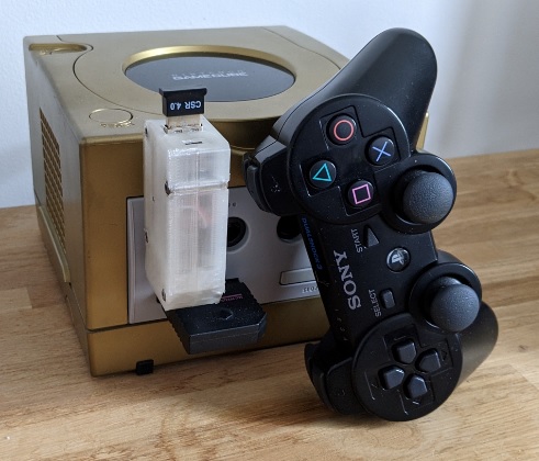
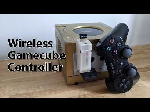
An arduino based bridge to connect a bluetooth PS3 controller to the Gamecube. Homemade Wavebirds, because the TV is too far from the couch.
This is nothing new, this is using two existing libraries : Nicohoods Nintendo to handle controller data sent to the GameCube, and PS3BT to use a PS3 controller.
- working!
- stick sensitivity ok!
- adapt the code for PS4 controller : this is only about using PS4BT functions rather than PS3BT.
- support Powera Gamecube Switch controller
- no rumble support
- inputs can be missed in case of mashing of buttons
For this project I used components I had gathering dust : Arduino Nano, BT dongle TBW-107UB.
- 16MHz Arduino (Nintendo library limitation) : 5E
- USB Host Shield : 5E
- USB Bluetooth2.1+EDR dongle or better : 8E (works fine with cheap bluetooth 4.0 dongle)
- 3.3V / 5V level logic level converter : 3E
- Gamecube cable extention : 5E Prices are rounded up, should be less than 26E.
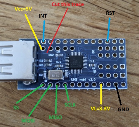
The cheap knockoff I ordered isn't well documented. I strongly recommend you do a continuity check to find out which pins connect to the MAX3421E : VCC (5V), VL (3.3V), INT, RST, SS, MISO, MOSI, SCLK, GND. The link to the datasheet is in the documentation section.
Mine looks like this, yours may be different. This board directly connects VCC to VL. Once trace shall be cut or there will be power supply issues.
First check which cable matches the following pins on the controller cable (male end).
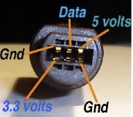 (image borrowed from https://hackaday.io/project/162348)
Wiring of the SS pin of the USB Host may be different depending on the Arduino board used. It is either D10 or D3.
| Arduino | USB Host | Gamecube |
|---|---|---|
| GND | GND | GND (both) |
| 3.3V | 3.3V | |
| 5V | Vcc | 5V |
| D3 | INT | |
| D8 | DATA* | |
| D10 | SS | |
| D11 | MOSI | |
| D12 | MISO | |
| D13 | SCLK | |
| RST | RST |
Data logic on the Gamecube is 3.3V, D8 pin shall be routed through a logic level 5V to 3.3V.
| Logic Level | Arduino | Gamecube |
|---|---|---|
| GND | GND | GND |
| LV | 3.3V | |
| HV | 5V | |
| HV1 | D8 | |
| LV1 | DATA |
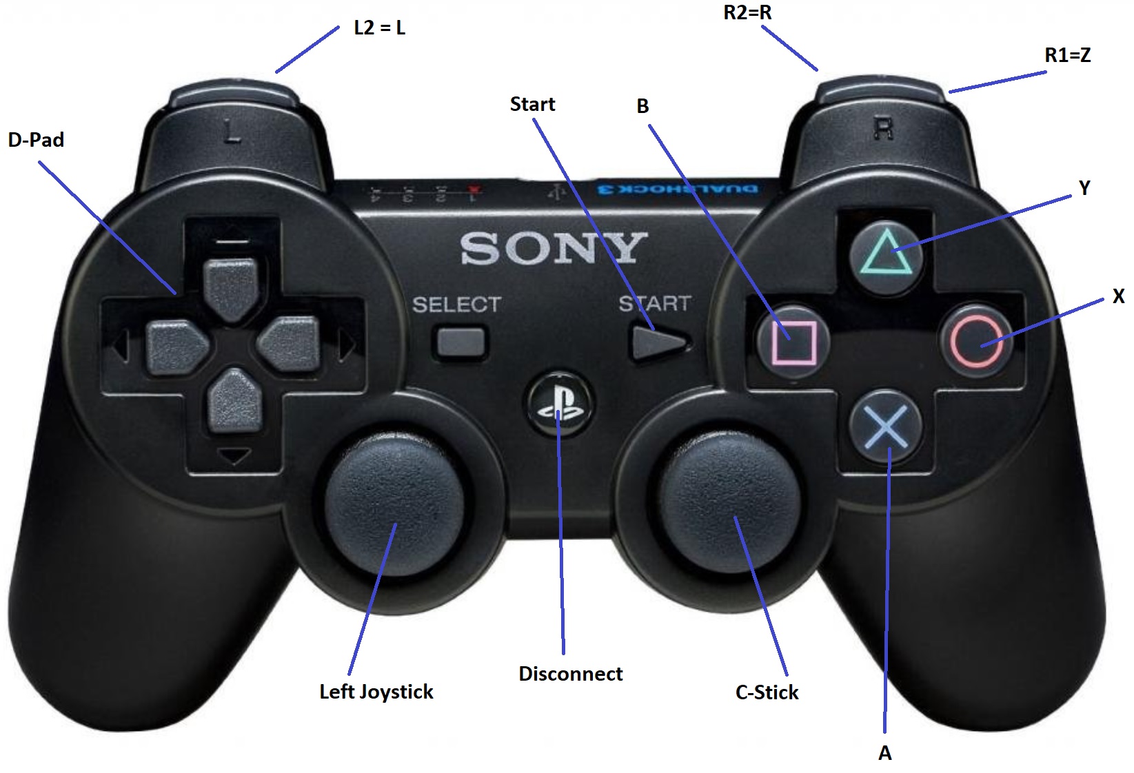
This is the default layout I chose. Feel free to change it : the switch position of the left stick and d-pad is sometimes not the best choice.
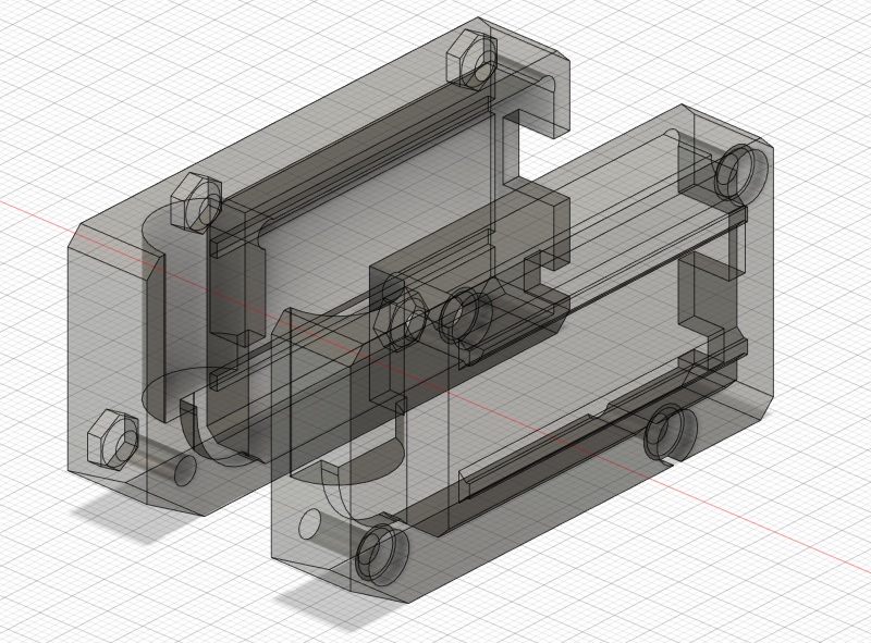
The enclosure comes in two parts, located in the stl subfolder.
They should be printed with layers = 0.2mm. Place the outside face on the bed to print without support.
To close the box, use 4xm3 screws, 2.2cm length.
- Nico Nintendo Library : https://github.com/NicoHood/Nintendo
- USB HOST v2.0 : https://github.com/felis/USB_Host_Shield_2.0
- MAX3421E : https://datasheets.maximintegrated.com/en/ds/MAX3421E.pdf
- DIY Wireless Gamecube Controller : https://hackaday.io/project/162348
- Why let the usb dongle stick out? --> This is part of the pairing process : the controller will need to be connected to the usb plug to get the MAC address of the BT dongle for the PS3 controller.
- Why not use an ESP32 which has integrated bluetooth? --> 1. I didn't have any spare esp32 when I did that project. 2. The Nintendo library from Nicohood has time sensitive routines coded in AVR assembly for 16MHz clocks. I didn't want to review timings as it was supposed to be a simple straightforward project to reuse old arduinos.
- It already exists, BlueRetro does it better! --> Yes it does, it supports more consoles, more controllers and more ports. My intent was to use simple and 'in my inventory' items. Also BlueRetro does it the right way by allocating one core for Bluetooth and one core for Wire. This project does both on a single core with a 10x lower clockspeed (but only one controller, can't do everything!). That may be a lead to support the Powera Gamecube Switch controller which was the initial goal of the project.