TL;DR: OOKwiz is an ESP32 Arduino library for receiving, analysing, decoding, encoding and transmitting On/Off keyed signals using a number of radios via RadioLib as well as a generic type. Radio plugins easy to build. Not just a library, also a versatile rx/tx OOK Swiss army knife. Used in a sketch that only calls the library's setup() and loop() functions, it prints output like below for received signals and provides a command line interpreter to set radio type, GPIO-pins used, etc. Settings are stored in flash on the ESP32 using SPIFFS. OOKwiz tries to read the data from messages, example: pulse(5906) + pwm(timing 190/575, 24 bits 0x1772A4) (all time in µs). That same format is among those accepted by the CLI transmit function, so on-the-fly experimentation is super-easy: just copy the string, change a few bits and transmit it back out.
5906,180,581,184,578,174,600,552,203,178,592,556,207,563,218,559,197,173,594,560,215,556,206,557,206,182,591,179,579,568,209,172,590,563,203,181,581,568,202,175,593,171,591,561,205,181,581,179,587
▀▀▀▀▀▀▀▀▀▀▀▀▀▀▀▝▀▝▀▝▀ ▝▝▀ ▝ ▝ ▝▝▀ ▝ ▝ ▝▝▀▝▀ ▝▝▀ ▝▝▀ ▝▝▀▝▀ ▝▝▀▝▀
25 pulses over 24287 µs, repeated 6 times with gaps of 132 µs
2010101100110101001101010010110011001100101100101,190,575,5906*6@132
 bin     min     avg     max  count
   0     171     190     218     24
   1     552     575     600     24
   2    5906    5906    5906      1
pulse(5906) + pwm(timing 190/575, 24 bits 0x1772A4)  Repeated 6 times with 132 µs gap.
On/Off Keying is the method of transmission used on various license-free radio frequencies to transmit signals. Remote controls for lights, garage doors, air conditioners as well as signals from outdoor weather stations and other sensors might be sent using On/Off Keying. The method of transmission is as basic as the name implies: no fancy modulations, just turn a transmitter on a given frequency on and off, and the timings of turning it on and off are used by the receiver to reconstruct a short digital message. Individidual pulses are usually in the order of about a millisecond long and messages are usually a low number of bytes.
'OOKwiz' is an Arduino library that can be used on ESP32 embedded devices to talk to a variety of radio modules for these frequencies on one side, and presents human-readable representations of the signals received on the other. Or the other way around: the user says what needs to be transmitted and the library transmits it. To use it from your software, or to use the provided examples to understand and transmit your own signals, you'd need to attach a radio for these frequencies. The WiFi/Bluetooth radio that is built into the ESP32 does not work for transmitting or receiving these signals.
The good news is that these radios are cheap and easy to come by. A variety of sellers sell radio modules based on some common transceiver ICs, some for well under $10 / €10 for next day delivery.


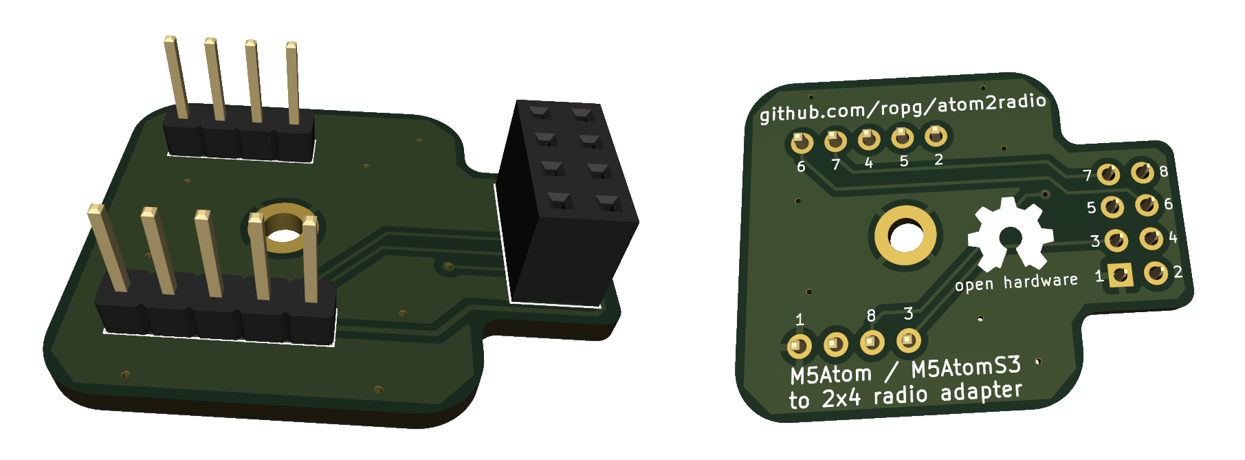
If you are going to be using an M5AtomS3 as the ESP, and a board with an 8-pin header as a radio, you could use my adapter board atom2radio.
Older modules are on a single fixed frequency, newer modules can be tuned to a specific frequency in the license-free band that they're made for. Some hook up to your Arduino using GPIO pins to directly turn the transmitter on and off and to see whether the receiver sees a signal. The newer ones need to be talked to via SPI. (In the case of on/off keying, the SPI communication is just used to set the radio to the correct state, the actual information is then sent/received via a GPIO pin.)
You can hook up any of the supported radio modules to any ESP32 device, board or module that has a few GPIO pins available for the user. I'll first describe an easy and known-to-work solution for when you're starting from scratch. This uses some hardware that is nice and compact and that OOKwiz is well-tested with. Then we'll describe hooking up some of the other supported radios. OOKwiz has various named setting that you will use to tell it about what radio you have, what GPIO pins it is connected to and much more. We'll get to how to do that in the 'Command Line Interpreter' section.


I used an ESP32 module I like a lot: the $7.50 M5AtomS3 Lite made by a Chinese company named M5Stack. (Probably also available from electronics distributors closer to you.) As you can see this is a nice, rugged, self-contained unit that has the USB-C connector already onboard.
Then you'll also need a radio module. The ICQUANZX CC1101 module currently (2024) sells for €8.99 next-day on Amazon, has the CC1101 radio chip OOKwiz supports, works well, and comes with an antenna-connector on the board and a little antenna.

Now you need to connect 7 pins on the M5AtomS3 with 7 pins on the radio module somehow. For a quick and easy experimenter setup, the simplest is to use 7 simple pin/socket jumper wires and you're done. Here's the wiring:
| M5AtomS3 | CC1101 | OOKwiz setting |  |
|---|---|---|---|
| G (GND) | 1 (GND) | ||
| 3V3 (3.3V) | 2 (VCC) | ||
| G39 | 3 (GDO0) | pin_rx & pin_tx | |
| G6 | 4 (CSN) | pin_cs | |
| G5 | 5 (SCK) | pin_sck | |
| G8 | 6 (MOSI) | pin_mosi | |
| G7 | 7 (MISO) | pin_miso | |

Being me I made a little circuit board to make these connections.

A slightly newer version of this board I called atom2radio and released as open hardware. You can have it produced by your favorite PCB manufacturing outfit.
All these modules are very similar in that you talk to them using SPI to tell them things like frequency and transmit power, but then for on-off-keying the actual reception and transmission are done via an active-low GPIO pin, which we connect to the ESP32 GPIO pin that we then set in our settings pin_rx and pin_tx. The SPI pins are easy: they are called MISO, MOSI, SCK and there's a chip-select that's either called CSN or CS.
The data GPIO pin is generally not the one used by these modules for interrupts, and cannot be remapped in software so you have to make sure that your module makes this pin available on its connector to the outside world, or be prepared to solder to the smaller radio-chip (module) that is on your larger module or breakout board. (The reason is that most people use these modules for FSK or LoRa, where information arrives in whole packets via SPI, whereas for OOK we are connected to the transceiver more directly.)
Even if your module provides a reset pin, if you';re short on GPIOs you can usually get away with not hooking it up and leaving pin_reset unset: the modules can also be reset via the SPI port. Below are a few details I learned about the supported modules.
Here the pin for the data is GDO0. You can set the tx_power setting to -30, -20, -15, -10, 0, 5, 7 or 10 to get that power in dBm. -30 dBm is 0.001 mW, 10 dBm is 10 mW. Default if unset is 10 dBm.
Data pin is DIO2. Set tx_power from -18 to 13 dBm for low power modules (RF69C/CW) or -2 to 20 dBm for high-power ones (RF69H/HC/HCW). Set tx_high_power in the latter case, or nothing will be transmitted.
The data pin is called DIO2, and there's definitely modules out there that do not offer that pin on their interface, so be aware. Allowed values range from -3 to 15 dBm when the RFO pin is used for the RF signal out. There is a built in power amplifier, which outputs through the PA_BOOST pin. Whether your hardware uses one or the other has to match the tx_use_rfo setting, which is set for RFO and unset for PA_BOOST. When using the RFO pin, tx_power can range from -3 to 15 dBm. On the PA_BOOST pin, 2 to 20 dBm operation is supported. Default if unset is 20 dBm, PA_BOOST pin.
The data pin is DIO2 again. Very much like the SX1278, the RadioLib class just implements a few methods that have different accepted value ranges.
These fixed-frequency transceiver modules are available for a number of ISM-band frequencies, both for 5V and 3V. Just four lines need to be hooked up to the ESP32, and the corresponding GPIOs set in pin_enable, pin rx_tx, pin_rx and pin_tx settings. Then set radio to aurel_rtx_mid, save and reboot.
These modules need a lot of pins set up that are driven high or low depending on whether you're transmitting or receiving. The functionality for this copied from rflink32 and nothing complex happens, so this should just work as is. If you're going to build new things, you will probably want to use one of these newer RadioLib-supported radio modules.
Once you have your ESP32 and radio hooked up, it's time to start playing with OOKwiz. All you need to do is fire up your Arduino IDE, install OOKwiz using the library manager and compile the following sketch:
#include <OOKwiz.h>

void setup() {
    Serial.begin(115200);
    OOKwiz::setup();
}

void loop() {
    OOKwiz::loop();
}
to get this:
OOKwiz version 0.1.0 (built Feb  1 2024 12:44:10) initializing.
No default settings found, setting factory defaults.
Mandatory setting 'radio' missing.
ERROR: Your radio doesn't set up correctly. Make sure you set the correct
       radio and pins, save settings and reboot.
CLI started on Serial. Type 'help' for list of commands.
If you have the M5AtomS3 / CC1101 combo as described earlier, all you then need to do is paste the following line into the input box above the serial output in your Arduino serial monitor and press return.
set pin_cs 6;set pin_miso 7;set pin_mosi 8;set pin_rescue 41;set pin_rx 39;set pin_sck 5;set pin_tx 39;set radio CC1101;save;reboot
You should now be seeing serial output when the unit receives packets.
If you have hooked up a different receiver, you need to tell OOKwiz how to talk to it by setting the appropriate setttings using set <setting name> <value>. If your radio is supported via RadioLib (currently CC1101, RF69, SX1276 and SX1278), you need to set the radio (via set radio <radio-name>) as well as the data pin used for transmitting and receiving. Typically with these radios that is done via the same pin, so you must set both pin_rx and pin tx to the same GPIO pin number. Then you must set the chip select pin for this SPI device by setting pin_cs.
If the SPI port on your ESP32 is where pins_arduino.h in your board files says it should be you don't need to set pin_miso, pin_mosi and pin_sck. If you do specify them, OOKwiz will configure the HSPI SPI port on your ESP32 to use these pins. If you'd prefer the FPSI or VSPI port, just set spi_port to VSPI or FSPI. Note that FSPI is often used internally by the module to connect the serial flash chip, so telling that to use different pins might result in the ESP32 crashing and rebooting.
On all the supported RadioLib receivers you can change the defaults for frequency (in MHz, default 433.92), bandwidth (in kHz) and bitrate (in kbps). On all but the CC1101 you can also set threshold_type (fixed, peak, or average, peak is default) and threshold_level (default 6).
If your ESP32 board or device has a button, this is the time to set it up so you can interrupt the OOKwiz radio inittialization. That way, if you hold that button pressed while the ESP32 resets, you can escape the endless boot-loop that might result if you set the wrong GPIO pins. Set the pin number for your button in pin_rescue, and enter set rescue_active_high if the GPIO goes high when the button is pressed.
Now enter save; reboot and hopefully watch OOKwiz report that it can talk to your radio.
OOKwiz version 0.1.0 (built Feb  2 2024 19:02:15) initializing.
Loaded settings from file 'default'.
Radio plugins loaded: RF69, CC1101, SX1278
Radio CC1101 selected.
Initializing radio.
Radio CC1101: SPI port HSPI, SCK 5, MISO 7, MOSI 8, CS 6, RESET -1, RX 39, TX 39
CC1101: Frequency: 433.92 Mhz, bandwidth 232.0 kHz, bitrate 9.600 kbps
CLI started on Serial. Type 'help' for list of commands.
You should now be seeing output whenever on/off-keyed signals are received.
Set something wrond, stuck with a continuously rebooting ESP32 and haven't configured a rescue-button? Simply upload your sketch again from the Arduino IDE, this time with "Tools / Erase all flash before sketch upload" enabled. Remember to turn that off again, or you'll keep erasing your settings every time you upload a new sketch.
If you type help in the Arduino IDE input field and press enter, you'll see:
OOKwiz version 0.1.0 Command Line Interpreter help.

Available commands:

help               - prints this message
set                - shows all the configuration settings
set x              - sets configuration flag x
set x y            - sets configuration value x to y
unset x            - unsets a flag or variable
load [<file>]      - loads the default saved settings, or from a named file in flash
save               - saves to a file named 'default', which is what is used at boot time.
save [<file>]      - saves the settings to a named file in SPIFFS flash
ls                 - lists stored configuration files in SPIFFS flash
rm <file>          - deletes a configuration file
reboot             - reboot using the saved defaults
standby            - set radio to standby mode
receive            - set radio to receive mode
sim <string>       - Takes a RawTimings, Pulsetrain or Meaning string representation and
                     acts like it just came in off the air.
transmit <string>  - Takes a RawTimings, Pulsetrain or Meaning string representation and
                     transmits it.

rm default;reboot  - restore factory settings
sr                 - shorthand for "save;reboot"


See the OOKwiz README.md on GitHub for a quick-start guide and full documentation
As you can see there's a list of commands there. Most important right now is to understand that there are settings and that you can see them all by simply entering set, change them by entering set <setting-name> <value> and remove them by entering unset <setting-name>. Some settings are flags and don't need a value, they can simply be turned on and off with set <setting-name> and unset <setting-name>. Once you have set up the settings that tell OOKwiz about your radio, you can save the settings and reboot by entering save;reboot (or sr for short).
If OOKwiz is happy with your radio settings, now is a good time to play around. Press buttons on the remotes you have and see what shows on the Arduino IDE serial monitor. Note that there's three formats for the data to be displayed: once as a RawTimings string that shows the microseconds (µs) between transitions.
5906,180,581,184,578,174,600,552,203,178,592,556,207,563,218,559,197,173,594,560,215,556,206,557,206,182,591,179,579,568,209,172,590,563,203,181,581,568,202,175,593,171,591,561,205,181,581,179,587
Next up are the data visualizer and the summary. The visualizer shows you the current packet as black stripes. There's two pixels per character using unicode blocks, and by default each pixel denotes 200 µs. Note that to make sure everything is visible, each transition takes at least one pixel. While the overall timing may thus be slightly off, it's a very good way to see what the signal looks like. The summary tells you what was received in words.
▀▀▀▀▀▀▀▀▀▀▀▀▀▀▀▝▀▝▀▝▀ ▝▝▀ ▝ ▝ ▝▝▀ ▝ ▝ ▝▝▀▝▀ ▝▝▀ ▝▝▀ ▝▝▀▝▀ ▝▝▀▝▀
25 pulses over 24287 µs, repeated 6 times with gaps of 132 µs
Then below you see the String representation of a Pulsetrain, which doesn't store the times between transitions, but just the 'bin' in which the timing falls. The conversion from RawTimings to Pulsetrain loses the individual timings of each transition, but what that does mean is that two transmissions of the same data will lead to the same Pulsetrain. The average time for each group of transitions in µs is shown after the transtions, separated by commas. Lastly, if multiple transmissions of the same data were received, the Pulsetrain notation will show the number and the number of µs between packets.
2010101100110101001101010010110011001100101100101,190,575,5906*6@132
Next is the Pulsetrain's 'binList', which shows a few more statistics about each bin, such as the minimum and maximum transition lengths in each bin and the number of transitions of that length received in total.
 bin     min     avg     max  count
   0     171     190     218     24
   1     552     575     600     24
   2    5906    5906    5906      1
Then at the end comes the true magic of OOKwiz: is possible OOKwiz will try to decode the signal and tell you what different components it is made of. For that, it tries to convert the Pulsetrain into a form called Meaning.
Data can be encoded in these signals in a number of different ways. Two popular ways that OOKwiz decodes by default are pulse width modulation (PWM) and pulse position mudulation (PPM). In PWM, a short transmission followed by a longer gap means one state of a bit, while a long transmission followed by a shorter gap represents the other state.

In pulse position modulation (PPM), the length of the transmitted pulses (or the length of the gaps between them) differs, so one state of a bit takes longer to transmit than the other.

In the case of our example, it thinks there was a preamble (starting pulse) or 5906 µs and then 24 bits of PWM-modulated data. Written in Meaning form, the packets looks like:
pulse(5906) + pwm(timing 190/575, 24 bits 0x1772A4) Repeated 6 times with 132 µs gap.
Often, you'll see only one byte change if you press a different button on your remote. For more complex transmissions such as weather stations, you'll need a bit more experimentation to see which bits are used to convey what meaning.
All three formats for writing a packet: RawTimings, PulseTrain and Meaning, can also be supplied as argument to transmit. So if you enter any one of these commands:
transmit 5906,180,581,184,578,174,600,552,203,178,592,556,207,563,218,559,197,173,594,560,215,556,206,557,206,182,591,179,579,568,209,172,590,563,203,181,581,568,202,175,593,171,591,561,205,181,581,179,587
transmit 2010101100110101001101010010110011001100101100101,190,575,5906*6@132
transmit pulse(5906) + pwm(timing 190/575, 24 bits 0x1772A4) Repeated 6 times with 132 µs gap.
you end up transmitting the packet from our example. Note that the last form makes it very convenient to just change a few bits in the data to see what happens.
As you've already seen, the minimal program to interact with OOKwiz sets up the serial port, calls OOKwiz::setup() and then has OOKwiz::loop() in its own loop() function. The OOKwiz class has more static methods, that allow for starting and stopping reception, transmitting and simulating packets, making your own code able to do the same things one can also do via the Command Line Interface. Click here for a full list of the available functions in OOKwiz:: and how to use them.
Your code can set and unset all of OOKwiz' settings, as well as read and write them to files in the SPIFFS flash file system. This allows you to create a program that does not depend on flash at all: simply set all the deviations from the factory settings and call OOKwiz::setup(true), the true makes OOKwiz ignore the settings in the flash file 'default' that it would normally load.
Your code can receive all the packets that OOKwiz sees by setting up a callback function and telling OOKwiz about it. Here's an example:
#include <OOKwiz.h>

void setup() {
    Serial.begin(115200);
    OOKwiz::setup();
    OOKwiz::onReceive(receive);
}

void loop() {
    OOKwiz::loop();
}

void receive(RawTimings raw, Pulsetrain train, Meaning meaning) {
    Serial.println("RECEIVE TRIGGERED");
}
This will simply print a message underneath OOKwiz' own output for each packet, but it shows that the function was called each time a packet came in. Make sure you define your own function exactly like this one. You can chnage the names of the function and the arguments, but your function must accept all three, in this order. Also note that the argument to OOKwiz::onReceive() is just the name of the function, without parenthesis.
So your code can see all the packets received, and it gets three representations of it to look at. Let's have a look at all three.
The first representation is an instance of the RawTimings class. It holds the exact times between the transitions of the signal turning on and off. These times are held in an std::vector container holding the transition times as an array of 16-bit unsigned integers. In the above code example, the String representation of this could be printed with Serial.println(raw.toString()), but you'll notice OOKwiz already prints these, it's the first line of the output for each packet. If you want to access these values for something, you could do:
for (n = 0; n < raw.intervals.size(); n++) {
    doSomethingWith(raw.intervals[n]);
}
If you don't need the index (the value of n), you can even do:
for (auto t : raw.intervals) {
    doSomethingWith(t);
}
The RawTimings class contains functions to convert to and from the String representation as well as to and from Pulsetrain, which we'll be look at next. Click here for a complete list of functions to execute on a RawTimings instance.
The next format the data comes in is a little more involved. Here OOKwiz has taken the intervals in the packet, sorted them by length and then made 'bins' for each cluster of intervals that are similar. It does this with the help of the setting bin_width, which defaults to 150 µs. If you look at the data OOKwiz prints about a packet, the majority of the lines are output from function in the Pulsetrain class. Here's our example packet again:
5906,180,581,184,578,174,600,552,203,178,592,556,207,563,218,559,197,173,594,560,215,556,206,557,206,182,591,179,579,568,209,172,590,563,203,181,581,568,202,175,593,171,591,561,205,181,581,179,587
▀▀▀▀▀▀▀▀▀▀▀▀▀▀▀▝▀▝▀▝▀ ▝▝▀ ▝ ▝ ▝▝▀ ▝ ▝ ▝▝▀▝▀ ▝▝▀ ▝▝▀ ▝▝▀▝▀ ▝▝▀▝▀
25 pulses over 24287 µs, repeated 6 times with gaps of 132 µs
2010101100110101001101010010110011001100101100101,190,575,5906*6@132
 bin     min     avg     max  count
   0     171     190     218     24
   1     552     575     600     24
   2    5906    5906    5906      1
pulse(5906) + pwm(timing 190/575, 24 bits 0x1772A4)  Repeated 6 times with 132 µs gap.
The first line is the String representation of the RawTimings as discussed above., the second line its visualizer() representation. Then the third line is what's printed by Pulsetrain's summary() function. The fourth is the Pulsetrain's toString() representation where you can see which 'bin' each interval falls into, as well as the average duration for intervals in each bin. The next four lines are the binList(): more detailed information about the distribution of interval lengths in each bin.
As you can see, Pulsetrain holds data about a packet and because the packets are written in a form that is the same every time, packets can be compared, and only packets that are different are presented. What that means is that when your receive function gets called, it only gets the RawTimings for the first packet. All identical repeat packets received immediately after were only used to increase the repeat counter and measure the minimum gap between packets.
If packets you are interested in are not sufficiently decoded to a Meaning instance, the Pulsetrain is probably the best starting point for making sense: your code can access the string of bin numbers that the packet has been reduced to as an std::vector of unsigned 8-bit integers in somePulsetrain.transitions. An std::vector holds information about the bins as type PulseBin. There's a host of functions and properties of the instance available, click here for a detailed description.
Meaning instances represent the highest level of abstraction: in the conversion to this format, an attempt is made to decode the packet and derive meaning as represented by the last line of the example packet output shown above. As you can see, the packet has been reduced to a long pulse (also called a preamble) of 5906 µs, followed by 24 bits of PWM encoded data. Here's a receive function example for accessing this data.
void receive(RawTimings raw, Pulsetrain train, Meaning meaning) {
    if (
        meaning.elements.size() != 2 ||
        meaning.elements[0].type != PULSE ||
        !tools::between(meaning.elements[0].time1, 5800, 6000) ||
        meaning.elements[1].type != PWM ||
        !tools::between(meaning.elements[1].time1, 175, 205) ||
        !tools::between(meaning.elements[1].time2, 560, 590) ||
        meaning.elements[1].data_len != 24
    ) {
        return;
    }
    // .data() on an std::vector gives a pointer to the first element
    uint8_t *data = meaning.elements[1].data.data();
    Serial.printf("Data received 0:%02X 1:%02X 2:%02X", data[0], data[1], data[2]);
}
As you can see this code ignores any packet that does not have the right length preamble or does not encode 24 bits using PWM with the correct timings. The fact that the space and mark times for the PWM are averages makes it possibe to make the bounds fairly narrow and reject packets that do not match the exact characteristics we're looking for. (tools::between() is a convenience function that comes with OOKwiz which merely checks if a value lies between two other ones.)
There's four kinds of MeaningElement, denoted by their type property: PULSE, GAP, PWM and PPM. The first two have their durations in time1, PWM stores 'space' and 'mark' timings in time1 and time2, and PPM stores 'space', 'mark' and 'filler' timings in time1 through time3. To transmit a packet like the one above, one could write:
#include <OOKwiz.h>

void setup() {
    Serial.begin(115200);
    if (OOKwiz::setup()) {
        Meaning newPacket;
        newPacket.addPulse(5900);
        uint8_t data[3] = {0x17, 0x72, 0xA4};
        // 190 and 575 are space and mark timings, 24 is data length in bits
        newPacket.addPWM(190, 575, 24, data);
        newPacket.repeats = 6;
        newPacket.gap = 130;
        OOKwiz::transmit(newPacket);
    }
}

void loop() {
    OOKwiz::loop();
}
A complete list of functionality surrounding Meaning instances can be found here
Whatever your radio is, the OOKwiz radio plugin just needs to know how to initialize your radio after startup, and then how to switch it between any of three modes: tx, rx and standby. The rest of OOKwiz just expects received data on the GPIO set in rx_pin and expects to transmit when it wiggles tx_pin. By default these pins are active low, meaning a transmission is when they go to ground. You can reverse that with the rx_active_high and tx_active_high settings. Take a look at the the existing plugins and you can probably figure out how to make your own. Just make sure MAX_RADIOS in config.h is at least the number of radio plugins you want to load, and include your plugin from the file RADIO_INDEX.
You really only need to implement the four function overrides you see in all the other plugins and you'll have a plugin. But if you care about the internals of it: the macros at the beginning and end of the plugin are defined in Radio.h and will show you that the plugin is actually an instance of the Radio class. Here is the generated documentation for that class. You'll see there's an auto-register trick that causes the plugins to be instantiated and their name and pointer stored in the static store struct before the main code even runs. This is why all you need to do is include it in RADIO_INDEX and presto.
There is generated documentation, but you're probably better off just looking at the example plugins. These work very much like radio plugins, except here the goal is to override the receive() and transmit() virtual functions.
The first, receive() gets the three representations of a packet and is to return true if it determines that this packet belongs to it, at which point OOKwiz will stop presenting the packets to further plugins. Next to returning true, the plugin can do whatever actions you see fit: provide serial output in rflink format or in more human-readable form, update the information for an MQTT client, adjust the presentation of a matter device via Wifi, you name it. Note that the order in which the plugins are included from DEVICE_INDEX determines the order in which plugin's receive() get to see (and thus claim, if they return true) the packets.
Your plugin's transmit() function is handed a String whenever the static function Device::transmit() is called with your plugin's name and a String to be transmitted. The format can be whatever you want it to be, OOKwiz is just passing it on. From the Command Line Interpreter, you may enter either "transmit :" or "10;;" to transmit something via a given device plugin.
Below is a description of most of the relevant guts of OOKwiz, as coded in OOKwiz.cpp. Don't worry of you don't understand everything at first glance. It's there for reference and so you don't need to puzzle it together from code comments if you need to understand what's going on.
OOKwiz uses Interrupt Service Routines (ISRs) to do the real-time aspect of receiving packets. Because all this work is done at this level, your program's loop() doesn't have to call OOKwiz::loop() often enough to catch every bit transition, but only often enough to pick up every processed packet. One of these ISRs is called for every transition of the receiver data GPIO pin as set in pin_rx. Normally it interprets a low voltage on this pin to mean there's a transmission received, and a high voltage to mean silence. This can be inverted by setting rx_active_high.
Things start with the internal enum variable rx_state is set from RX_OFF to RX_WAIT_PREAMBLE. This happend after everything is initialized when you call OOKwiz::setup(), or after you called OOKwiz::receive() if your program had interrupted reception earlier. If the ISR is called after a transition while rx_state is RX_WAIT_PREAMBLE, it will look at the time since the previous transition in microseconds. If the transition was to a silent state (i.e. if a transmission just ended) and the transmission lasted more than first_pulse_min_len µs, it assumes a new transmission has started and changes rx_state to RX_RECEIVING_DATA. From then on, every transition the time since the last one is recorded in a RawTimings instance.
If the time since the previous transition is less than pulse_gap_min_len it is assumed this was caused by noise, and the value from the noise_penalty setting is added to the internal variable noise_score. Every valid (long enough) transition after that will subtracts 1 from this score (but never below zero) because apparently valid data is still being received. If noise_score reaches noise_threshold, the packet is considered to have ended and passed on for noise fixing and further processing.
Packets can also end when a second ISR is called. This is a timer ISR, and it is called pulse_gap_len_new_packet µs after any transition. So if a transmission or a silence takes longer than that, we assume this is either (in the case of silence), the end of a transmission, or (in the case of a tranmission), a preamble to the next one.
In the factory defaults, both first_pulse_min_len and pulse_gap_len_new_packet are set to 2000 µs, (i.e. 2 ms), meaning any packet must start with a transmission of at least that length to be considered. You can set this much lower to start on any sequence of long-enough bits. Note that if you lower pulse_gap_len_new_packet too much, you risk processing packets before they're finished.
Once they're considered ended, packets are passed on for further processing. First it is cheked whether the packet has at least as many pulses as set in min_nr_pulses (default 16). If that is the case, it is checked for noise transitions, those lasting shorter than pulse_gap_min_len, and the transitions directly before and after are merged with this one, effectively pretending that the noise never happened. If, after de-noising like this, the number of pulses is still over min_nr_pulses and under max_nr_pulses (default 300), the packet is passed on, otherwise it is ignored.
There's actually three buffers being used at the ISR level. They are pairs of RawTimings and Pulsetrain instances, and they are called isr_in, isr_compare and isr_out. First of all, the raw timings that have been received and processed in isr_in.raw so far are normalized to a Pulsetrain in the accompanying isr_in.train. Then this train is compared to the train in isr_compare, if there is one. If there isn't one, isr_in is simply moved to isr_compare and the system returns to watiting for a next packet. isr_compare is sort of a holding station where any received packet has to wait for the amount of µs set in repeat_timeout to see if the same packet comes in again. If it does, that packet is ignored, except the repeats counter on the packet in isr_compare is increased and the smallest gap between received packets is recorded in the packet's gap variable.
As soon as repeat_timeout expires or a new and different packet arrives, the packet in isr_compare is moved to isr_out, ready to be picked up by OOKwiz::loop() for final processing.
OOKwiz::loop() stores the RawTimings and Pulsetrain of the packet in its own temporary storage and empties isr_out so that the next packet can be put there. It generates a Meaning instance from Pulsetrain and prints all sorts of information about them, including their string representations, as individually enabled by various settings whose names start with print_. It then provides the RawTimings, Pulsetrain and Meaning to the user callback function, if one is set using OOKwiz::onReceive(), as well as passing them to all device plugins (see section about device plugins) that were not disabled in the settings.
OOKwiz::loop also calls the CLI::loop() function to see if there's any serial data that needs to be processed, and once a second it sees if it needs to update any of the the internal variables described above that affect the recognition and processing of packets from the settings.