User Documentation
One of the goals of the openETCS project is to "Provide a tool chain and process/methodologies for developing an on-board software that can fulfill the CENELEC requirements for SIL4 software".
The tool chain consists of activities to support producing certifiable software such as:
- Software planning
- Requirements tracing
- Tool confidences
- Documentation/report production
- Testing
- Verification and validation
- a continuous automated build system,
- mechanisms to upgrade tools in the platform,
- mechanisms to add tools to the chain at a later stage (without breaking compatibility),
- modification and change control manager,
- tool chain documentation system.
The current implementation of the tool chain, e.g. the set of tools already integrated are depicted in the following diagram. The diagram groups the tool by activities. The green boxes represent the tool or feature already integrated, the yellow the work in progress and the red ones the soon-to-be integrated.

The openETCS tool chain is an eclipse product based on Eclipse-Kepler modeling tools, that groups a set of features or plugin used to implement the openETCS design process.
The list of the current integrated plugin and feature are the following:
https://github.com/openETCS/toolchain/wiki/Introduction-to-Git
WP3 imposes some restrictions on the use of SysML. Please consult the [Modeling](https://github.com/openETCS/modeling/wiki) for more information.
The Data Dictionary contains information from the SRS that should be shared between all created modeling artifacts. A way to make such shared data available is a SysML package which contains all the information of the Data Dictionary. A SysML Model can import this package and then reuse all of its contents.
The initial model is automatically generated from Bitwalker (XML) version of subsets 26-7, 26-8 of the specification. A transformation is provided as standalone plugins. This is a one-shot transformation, once the model is used in production replacing it may result in many manual rewiring in user models. Regenerating this model often is bad practice.
The current Data Dictionary model is DataDictionary.zip. This tutorial explains how to add the model to your project.
Users should add their own types to the data dictionary, we recommend to use a distinct package in case regeneration has to be performed. This way we can easily extract user defined types from generated ones.
For more details refer to page Data-Dictionary-Plugin, for user workflow refer to page Data-dictionary-user-workflow.
The scope of a single requirement ID is a paragraph of text. Requirement IDs are hierarchical. The hierarchy is a direct mapping of the hierarchy in the original subset026 text. Levels are separated by a dot. There is a requirement at each level (i.e. you may truncate the requirement ID to any level and it remains valid).
How to?
Let us take an example:

Suppose we want to identify the fifth paragraph in the above example i.e ("End Of Mission is performed").
1.Find the current running number of the baseList. That is the list which includes the chapter number. In this example this number equals 3.5.3.7. This is our initial ID. 2. Count the number of paragraphs in this list item starting with 1 and append this number in square brackets to the ID if it is greater than 1. Note: For the first iteration in the example there is only one such paragraph (If the establishment...). Hence, we do not append anything. In the second iteration there are two such paragraphs (The on-board shall... + If this request is not...). Hence, the second one will receive an [2] appendix. Until you arrived at your target paragraph: Append any running number of sublists and remove leading or trailing characters (such as braces). If the current sublist is bulleted then the level string always becomes [*][n](with n being the running number of that bullet starting at 1). Prefix this new level with a dot (.) and append it to the ID. Note: a) is the identifier of one such sublist item. The trailing brace will be removed. The bullet points form another (less significant) sublist.
This will result in the following requirement ID:
3.5.3.7.a[2].[*][2]
Requirements are managed with Eclipse RMF. Please check out the RMF documentation for now:
- Tutorial
- Note that the RMF documentation is included in the built-in Help of openETCS.
The Tracing Features allow the linking of *ProR Requirements* and *SysML Model Elements*. This is realized within the requirements model by using the internal links (SpecRelations) and requirements that act as proxies to the SysML Model element. Note that both, links and proxies, can be extended with additional attributes.
Change Tracking is done by using the Change Management Plug-in described below.
This section describes how the tracing feature is configured and used.
Resources:
- Code available at https://github.com/openETCS/toolchain/tree/master/tool/bundles/org.openetcs.pror.tracing
- Specification available at https://github.com/openETCS/toolchain/tree/master/PositionPapers/FormalMind
We assume that you have openETCS installed, and open with a ProR requirements model and a SysML model.
We suggest switching to the Papyrus Perspective, to have all relevant Views on the screen. (Window | Show View | Other...)
A number of datatypes must be created that are being used in the tracing configuration. Please create the following elements, or make sure that they exist. The names are just recommendations that are used throughout this chapter:
- You need the requirements model open and focused.
- The datatype configuration dialog is opened via ProR | Datatype Configuration....
- Datatypes for the Proxy Element:
- Proxy Type: This is a Spec Object Type for the proxy elements.
- Description: This is an Attribute Definition String that is a child of Proxy Type:. This is where the URL to the linked element is stored.
- T_Proxy: This is the Datatype Definition String that is associated with Proxy Attribute:.
- Datatypes for the Link Element:
- Link Type: This is a Spec Relation Type that connects the Proxy Type: with the requirement.
- You need the requirements model open and focused.
- Select ProR | Presentation Configuration
- From the dropdown Select Action... pick Tracing
- Upon selecting the newly created configuration element, the property view shows 7 entries:
- Attribute Names: Enter the attribute name you picked earlier (Description). Note: That you need to type the name exactly as you created it earlier.
- Datatype: The datatype you created earlier (T_Proxy).
- Link From Target: Whether the source of the link is the SysML Proxy, and the target the requirement, or the other way around.
- Link Type: The SpecRelationType you created earlier (Link Type).
- Package Prefix: (Advanced users) This is the package namespace of the Java object that is being dragged on the requirement. If the namespace fits the beginning of the dragged object, then the drop operation is enabled. The default (org.eclipse.uml) fits all Papyrus model elements. Changing this allows to configure multiple tracing integrations without interfering with each other.
- Proxy Attribute: The attribute from the Proxy attribute, from the drop down (Description (String) Proxy Type)
- Proxy Type: The SpecObjectType you created earlier (Proxy Type:)
Traces are established with Drag&Drop from the Papyrus Model Explorer to the ProR Specification Editor. Thus, both must be visible.
The model explorer will be empty if the Papyrus editor is not visible. Therefore, you must rearrange the editors so that both the ProR Requirements Editor and Papyurus Model Editor are visible at the same time. Here is an example on how this can look like:

- Model Changes from the Papyrus Model will propagate upon saving.
- The current implementation is not very efficient. Should you encounter performance problems, things can be improved. Note, however, that many performance issues are caused by Papyrus (e.g. opening a model can take several seconds). This has nothing to do with this plugin.
- The original spec was asking for a change tracking mechanism. This, too, will be available as part of Toolsprint 7. In fact, this will be realized with the existing suspect link plugin. Due to a pending ProR release, this is not available yet.
- Help improving the documentation by adding more information here.
This features allows traces to be flagged, if source or target of that link has changed. Currently, this works for all links within requirements, as well as for links between requirements and SysML model elements (created with the tracing feature.
For now, you need to explicitly install this feature, as described above.
The feature needs to be configured only once as follows:
- You need a SpecRelationType for this feature.
- The SpecRelationType must have two boolean attributes. We recommend calling them SourceChanged and TargetChanged.
- Don't forget to create a Boolean Datatype for the boolean flags (e.g. T_Changed).
- The SpecRelationType should now look like this (here it's called Proxy Link Type):

- You also need to configure the Link Management Pesentation.
- Go to ProR | Presentation Configuration...
- From the Select Action... drop-down, select Linkmanagement. This should be configured as shown below:

- The fields have the following values:
- Datatype - the datatype of the boolean flags (earlier called T_Changed).
- Link Relation Type - the type we created earlier.
- Source Status - the attribute of the flag that indicates that the source changed.
- Target Status - the attribute of the flag that indicates that the target changed.
- This completes the configuration.
The use is simple:
- If the source or the target of a link changed, the corresponding flag will be set, indicated by a yellow triangle with an exclamation mark.
- The flag can also be set manually be double-clicking on the cell.
- The flag can be reset by double-clicking as well (this should happen after verifying that the trace in its current form is still valid.
- If you link to a an element that is not a requirement (e.g. a SysML model element), you need to save the model for the flag to be set.
This section mainly concerns verification of openETCS architecture expressed in SysML through Scade System.
Scade System tool is used in OpenETCS project to design SysML architecture model. The format of produced model is compliant with open source Eclipse Papyrus and it is therefore possible to read SysML architecture model with Papyrus.
ReqCycle solution, an open source solution dedicated to support traceability that is hosted by PolarSys industrial working group of Eclipse foundation, can create traceability links with Papyrus models natively. ReqCycle project is defined here: https://www.polarsys.org/projects/polarsys.reqcycle
So it is a quite simple solution with no additional development and only user level configuration.
ReqCycle 0.8.1 for Luna is integrated in OpenETCS tool chain and is therefore available when you install the tool chain.
There is a predefined configuration for openETCS that can be downloaded here: https://github.com/openETCS/toolchain/blob/master/T7.3/TraceabilityArchitecture/reqCycleUse/openETCSReqcycle-conf.zip
Note: you can also define your own configuration after following ReqCycle full tutorial available here: https://polarsys.org/wiki/Model_Based_System_Engineering_tutorial_with_ATM_system
If you use predefined openETCS configuration, please follow the next steps:
- In openETCS tool chain, switch to ReqCycle perspective.
- Go to « ReqCycle » top menu and select « initialize configuration ». A popup is displayed.
- Say OK and select « openETCSReqCycle-Conf.zip » (from directory where you downloaded file previously).
- Restart tool chain (menu "File>restart"), that’s it
You will see that there is a custom requirement data model with one requirement type "SRSRequirement" with some custom attributes including "kind", "implement" (like in .ReqIF files) and also "fullyCovered" to manage requirement coverage by architecture (partial or full).
In "traceability types" you will see one relation defined: "ArchitectureVerification" that takes a requirement as source and a model element as target.
ReqCycle has to know requirements before it can support creation of traceability links to them.
First step is to import .ReqIF requirements stored and managed by ProR (in the future ReqCycle will have the capabilities to reference those requirements. For now, an import with copy is necessary).
- In openETCS tool chain, create a new Eclipse general project called "Reference Requirements" and import .ReqIF files, either with "import" contextual command from selected project, else by copy/paste of .reqIF files.
- Then go to « Requirement sources view » and create ReqIF requirement source for each Subset026 chapter .ReqIF file by following next steps:
- Create .ReqIF requirement source (for example for chapter 3):

- Fill requirement source data (first page)

- Do the mapping between .ReqIF file and ReqCyle custom requirement data model for openETCS


Now you can see the requirements in ReqCycle (for instance Chapter 4):


- Then create another Eclipse general project for model
- Import (or copy/paste) SysML model files from OpenETCS_EVC model.
- Load ETCS papyrus SysML model (in project explorer view, double click on openETCS_EVC element with Papyrus icon)
- click « cancel » on the first popup windows that is displayed about missing profiles (we do not care of missing Scade profiles for now)

You can use drag and drop between one requirement (from requirement view) and one model element (from model explorer view):

You can also use the traceability creator view:
- select source,
- click "+" icon at the right of source area
- select target
- click "+" at the right of target area
- click arrow button to display possible links: only "ArchitectureVerification" is defined, so click on it.

You can see all links created (and captured) from Traceability table view and can filter links by a string:

You can also remove some links from this table. Removal of links can only be done by end user from traceability table in « transverse links » mode
- Click « transverse links » button and select the Eclipse project that contains SysML model: it contains the traceability file (hidden file).
- Right click on link to delete, a popup menu shows, from which you can delete the links.

When you created all necessary trace links for a given requirement, you can set the coverage requirement attribute. * select the concerned requirement from requirement view
- open "properties" view (window>show view>... choose "properties view if not already open)
- go to "fully covered" attribute and select "true" in the combo box. By default, value is "false".

You can export all requirements and traceability links from File>export>Reqcycle>Xls and csv


Then you get some CSV file that can be open with Excel. Here is an illustration of result with two links:

Eclipse toolchain plug-in generates Eclipse Help documentation (a hierarchy of HTML files) and PDF documentation from toolchain repository.

It is necessary to create a Jenkins job to generate automatically toolchain documentation. This job launches mediawiki file cloning process from Github repository to the user’s local machine. In this way, toolchain documentation is cloned. Also, Jenkins job activates documentation generation running build.xml file using Ant to generate Eclipse help, PDF documentation and a table of contents dynamically.
Eclipse help HTML files and a PDF file are generated in "org.openetcs.toolchain\OpenETCS_toolchain" folder.
The following image shows generated Toolchain Documentation openETCS Guide available selecting Help | Help Contentsin the tool.

Tip: Subpage links should include real section name. Moreover, the spaces between words should be replaced with underscore. E.g. [[Documentation#Tracing_Requirements_and_SysML_Models|tracing]]
We assume that you have openETCS Toolchain and Jenkins installed.
- Jenkins job creation

- Jenkins job configuration
The following image shows Source Code Management section configuration. In this case, it has to be taken into account that openETCS Eclipse tool is placed in C:\ and the toolchain plug-in is located in “plugins” folder.

In order to automate the job execution, introduce @daily in the Build Triggers section to specify that the job will be executed daily. Anyway, the user could launch the job execution whenever he/she wants.

In the Build section, select Invoke Ant as Add build step option to allow Jenkins to locate and execute build.xml file using Ant. The path to the file should be specified using Build File textbox. From the previous example, the following path is needed:
C:\openETCS-win32_32\plugins\org.openetcs.toolchain

Finally, push Save button to save the job and its settings.
This document describes how the SysML elements are translated in B code by the SysML to B translator tool.
| Tag | Document |
| [1] | D2_4 Definition of the methods used to perform the formal description |
| [2] | SysML Modeling rules for SysML to B (MFR14-ARC-839) |
The generated B model has the architecture shown on Figure 1.
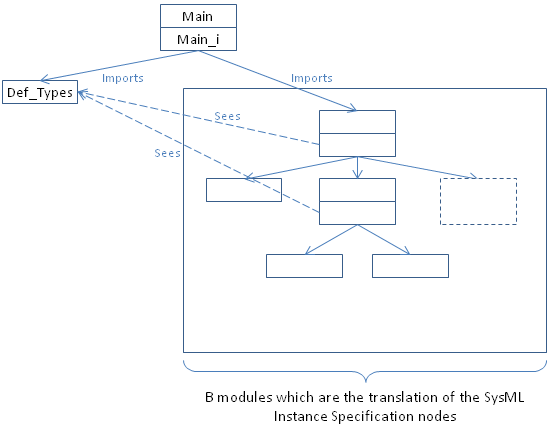 Figure 1: graphical representation of the architecture of the B model automatically generated by the translator tool
A root machine named Main is automatically generated. It has an operation named run_cycle which calls the schedule operation of the imported B machine. Figure 2 and Figure 3 shows the B code of the machine Main.
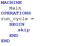 Figure 2: Main.mch
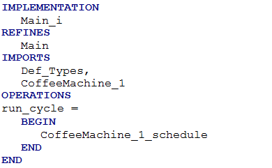 Figure 3: Main_i.imp where CoffeeMachine_1_schedule is the schedule operation of the B machine which corresponds to the root SysML Instance Specification
The machine Def_Types.mch is used to defined the enumerated sets that are used by the model. An example of the Def_Type code is given in Figure 4.
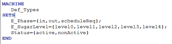 Figure 4: Def_Types.mch, where E_SugarLevel and Status are an example of a translation of SysML Enumeration Nodes. E_Phase is always generated
A B machine which is a translation of an instance of a SysML block can have inputs and outputs.
The scheduling of one B machine which corresponds to an instance of a SysML block must follow these steps:
- Set the value of the inputs: ''Write'' operations;
- Determine the value of the outputs: ''Schedule'' operation;
- Set the Value of the outputs: ''Read'' operations.
It is important to use the variable Phase for a B machine which is a translation of an instance of a SysML block that have a constraint. Indeed, a block constraint is translated to an invariant of the B machine (see Clause INVARIANT). This invariant is valid only when the new value of the outputs is set, so when Phase value is "out".
A SysML element typed with a Primitive Type Node will be translated to a B variable typed with a type which has the same name than the Primitive Node (see [2]).
For example, if a SysML Primitive Type called "NAT" is created, then a SysML element which is typed with this Primitive Type will be translated in B code to a variable typed with a type called NAT.
A SysML Enumeration node is translated in B code to a set. All the sets which correspond to an Enumeration Node are declared in the B machine Def_Types.mch.
A SysML element typed with a Data Type Node will be translated to several variables. One variable will be created for each property of the Data Type typed with a Primitive Type or an Enumeration.
An example is shown with the Figure 5 and Figure 6. The SysML output flow port MakeCoffee is translated in two B variables: MakeCoffee_CoffeeSelected and MakeCoffee_SugarLevel.
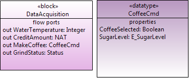 Figure 5: the block DataAcquisition has an output MakeCoffee which is typed with the Data Type CoffeeCmd
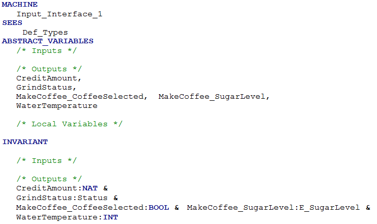 Figure 6: a view of the translation of the SysML block DataAcquisition. The output MakeCoffee is translated into two variables: MakeCoffee_CoffeeSelected and MakeCoffee_SugarLevel
A Flow Specification node is translated like a Data Type node.
For each instance of a block, defined with an Instance Specification node, a B machine is created. So, a B machine corresponds to a unique instance of a unique SysML block.
The generated B machine contains these B clauses:
- SEES
- ABSTRACT_VARIABLES
- INVARIANT
- INITIALISATION
- OPERATIONS
The SEES clause is used to see the B machine Def_Types which contains the enumerated sets used in the model.
In the ABSTRACT_VARIABLES clause are declared the inputs, outputs and local variables of the B machine.
The inputs variables of the B machine are the translation of the flow ports with "In" direction of the corresponding block.
The outputs variables of the B machine are the translation of the flow ports with "Out" direction of the corresponding block.
The local variables of the B machine are the translation of the properties of the corresponding block.
A variable called Phase can also be declared in this clause. The Phase variable is used when at least one constraint is added to the block which is translated in the B machine (see Clause INVARIANT).
An example of the ABSTRACT_VARIABLES clause is shown by Figure 7.
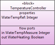
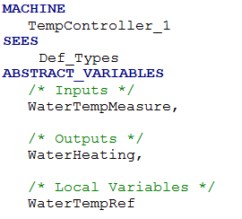 Figure 7: The ABSTRACT_VARIABLES clause of the translation of the block TemperatureController. There is no variable Phase because the block TemperatureController does not have a constraint.
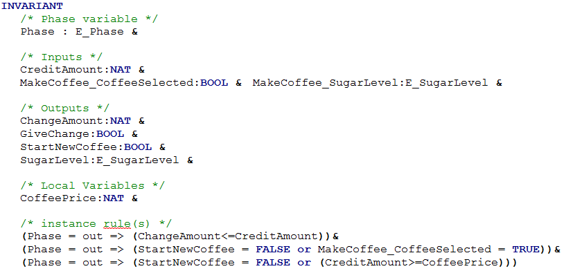
In the INVARIANT clause, the inputs, outputs and local variables of the B machine are typed.
Also, if they exist, the constraints of the translated block are added to the INVARIANT clause. In this case, the constraints shall be valid only when Phase variable value is at out. Phase variable is also typed in this clause.
The translated constraint of a block shall be verified only after the outputs calculation. The Phase variable is set to the "out" value when the outputs have been calculated (see B machines with imported machines). It is why the specific invariants of a B machine (the translation of a block constraint) are verified only when the Phase variable value is "out".
An example shown with the Figure 8: the block constraint "ChangeAmount<=CreditAmount" is translated in the invariant "Phase = out => (ChangeAmount<=CreditAmount)".
In the INITIALISATION clause of the B machine, the inputs, outputs, local variables and Phase variable (if it exists) are initialized with a non-deterministic substitution. All the variables are weak-initialized. Only the Phase variable is initialized to a specific value: In.
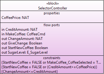
An example shown with the Figure 9.
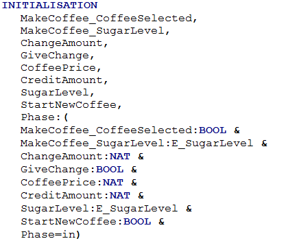 Figure 9: SelectorController block and the INITIALISATION clause of its translated B machine
The OPERATIONS clause of a B machine contains the following operations:
- Schedule operation: a schedule operation is generated for all the B machine which are the translation of an instance of a SysML block (see Schedule operation);
- Write operations: Write operations are generated for each input of the B machine (see Write operations);
- Read operations: Read operations are generated for each output of the B machine (see Read operations);
- Phase functions: when the B machine is a translation of an instance of a SysML block which have a constraint, then Phase_In and Phase_ScheduleReq operations have to be generated (see Schedule operation)
The generated B implementation contains these B clauses:
- SEES
- IMPORTS
- CONCRETE_VARIABLES
- INITIALISATION
- OPERATIONS
The SEES clause is used to see the B machine Def_Types which contains the sets used in the model.
The clause IMPORTS is created only when the SysML block which corresponds to the B implementation contains a part property.
The B implementation imports each B machine which corresponds to the value of the slots of its corresponding SysML instance.
For example, the block System has three parts: Acquisition, Ctrl and Outputs (see Figure 11). CoffeeMachine_1 is an instance of this block. It has three slots which define the value of the parts Acquisition, Ctrl and Outputs. These value are respectively the block instances Input_Interface_1, Controller_1 and OutputInterface_1 (see Figure 10). So the block instance CoffeeMachine_1 is translated into the B implementation CoffeeMachine_1_i which imports the B machines OutputInterface_1, Input_Interface_1 and Controller_1 (see Figure 12).
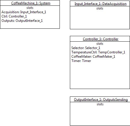 Figure 10: example of three Instance Specification nodes
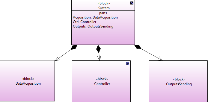 Figure 11: example of a simple model composed of four blocks
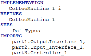 Figure 12: the IMPORTS clause of the B implementation of CoffeeMachine_1
The variables declared in the clause CONCRETE_VARIABLES are the same than the variables declared in the clause ABSTRACT_VARIABLES of the B machine (see Clause ABSTRACT VARIABLES).
In this clause, the variables are initialized to the default value specified in the SysML model.
Phase variable, when it exists, is initialized to the value "In".
A example is given with the Figure 13 and Figure 14. We can see that in the B generated code the variable MakeCoffee_SugarLevel is initialized to level2 because the property SugarLevel of the data type CoffeeCmd has a default value set to level2.
Same operation is defined in Clause OPERATIONS of abstract machines.
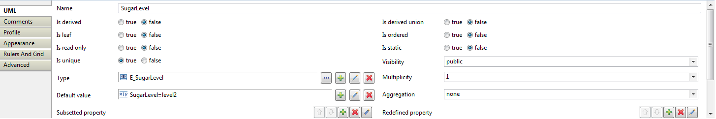
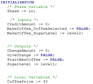 Figure 14: SelectorController block and the clause INITIALISATION of its translated B implementation
The Read operations are generated for each output of the B machine.
A Read operation of an output permits to access the value of the output produced by the owning B machine.
The name of a Read operation is the name of the output prefixed with "Read_".
A Read operation returns the value of the corresponding output.
Because a Read operation read the value of a B machine output, a Read operation is called at the third step of the B machine scheduling (see Scheduling), when the outputs have been calculated. So, if the B machine has specific invariants which are the translation of Block constraints, then these invariants have to be verified at the end of the Read operations. That is why the pre-condition Phase = out is added to the Read operation when the B machine is the translation of an instance of a SysML block which have block constraint.
An example of Read operations is given with the Figure 15.
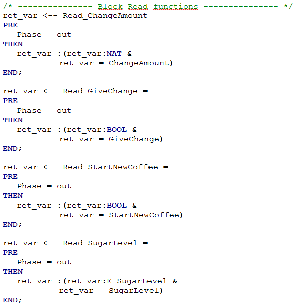
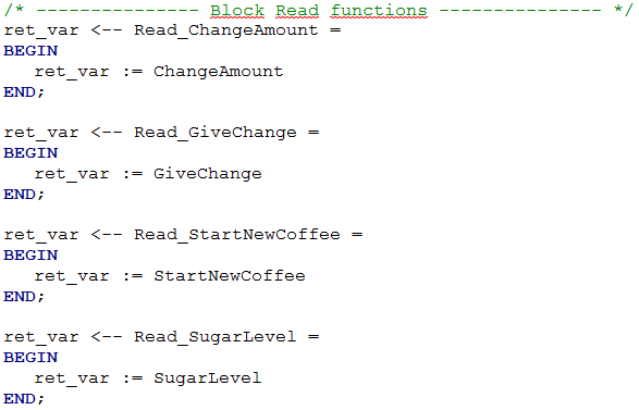 Figure 15: read operations for the outputs of the B module which corresponds to the block SelectorController. First the B machine, then the B implementation.
The Write operations are generated for each input of the B machine.
A Write operation of an input permits to modify the value of the input.
The name of a write operation of an input is the name of the input prefixed with "Write_".
A Write operation takes as argument the new value of the corresponding input.
Because a Write operation set the value of a B machine input, a Write operation is called at the first step of the B machine scheduling (see Scheduling). So, if the B machine has specific invariants which are the translation of Block constraint, then these invariants do not have to be verified at the end of the Write operations. That is why the pre-condition Phase = in is added to the Write operation when the B machine is the translation of an instance of a SysML block which have block constraint.
An example of Write operations is given in Figure 16.
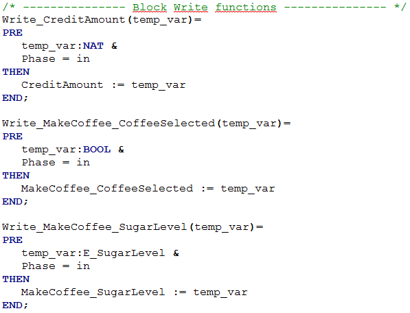
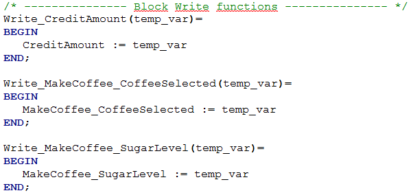 Figure 16: write operations for the inputs of the B module which corresponds to the block SelectorController. First the B machine, then the B implementation.
The Phase variable is set to one of these values: In, Out, ScheduleReq.
The value of the Phase variable is set to "In" by the Phase_In operation, and to " ScheduleReq " by the Phase_ScheduleReq operation. The Phase variable is set to "Out" by the Schedule operation of the same B machine.
The Phase_In and Phase_ScheduleReq operation are called by the Schedule operation of the owning B machine. An example of the specification and of the implementation of these operation is given by the Figure 17.
The Phase operation are generated only when the B machine contains invariant coming from SysML block constraint.
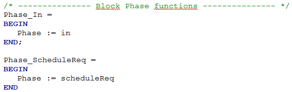 Figure 17: operation Phase_In and Phase_ScheduleReq. The specification is identical to the implementation of these operations.
Every B machine which is the translation of an instance of a SysML block has a schedule operation.
If the B machine does not import other B machine (because the B machine is the translation of an instance of a block which does not have parts), then the schedule operation is the behavior of the B machine. This schedule operation should be refined and implemented manually.
If the B machine imports other B machines (because the B machine is the translation of an instance of a block which contains parts), then the schedule operation manage the exchange of data between each imported B machine. Indeed, because the imported B machine are the translation of parts, the inputs and outputs of these machines shall exchange data.
The connection between the inputs and outputs of the imported B machines are deduced from the internal block diagram (ibd) of the block corresponding to the translated SysML block.
For example, the B machine Controller_1 is the translation of an instance of the SysML block Controller (see Figure 18) which is composed of the parts Selector, TemperatureCtrl, CoffeeMaker and Timer. The ibd of the block Controller shows how these parts are connected to each other and to their owning block (see Figure 19).
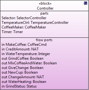 Figure 18: block Controller, which has four parts: Selector, TemperatureCtrl, CoffeeMaker and Timer
 Figure 19: internal block diagram of the block Controller.
The schedule operation of a B machine which have imported machines do these task for each imported B machine:
- Call the Phase_In operation of the imported B machine if the imported machine has specific constraints;
- Set the value of the inputs of the imported B machine by calling the corresponding Write Operations;
- Call the Phase_ScheduleReq operation of the imported B machine if the imported machine has specific constraint;
- Run the behavior of the imported B machine by calling the Schedule operation of the imported machine;
- Save into local variables the value of the outputs of the imported B machine by calling the corresponding Read operations.
For example, in Figure 19, parts Selector and TemperatureCtrl are the parts that shall be processed at first because their inputs are connected only to the inputs of the owning block Controller. Then, the part CoffeeMaker shall be processed because it is connected to the outputs of Selector and TemperatureCtrl. Finaly, the last part to be processed is Timer.
Note that the SysML to B translator tool does not manage yet the case of parts connected to each other in both directions, like the example depicted by the Figure 20. Thus, all the parts of a block shall be connected without cycle.
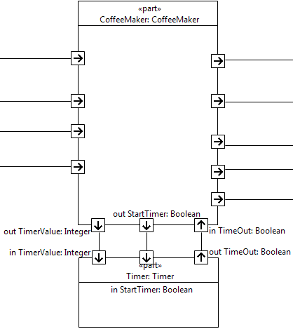 Figure 20: CoffeeMaker and Timer are connected to each other in both direction, CoffeeMaker transmits data to Timer and Timer transmits data to CoffeeMaker, which is forbidden
When all these tasks are done for all the imported machines, then the schedule operation set the value of the machine outputs with the value of the corresponding local variables.
As example, the generated code for the B machine that corresponds to an instance of the block Controller is shown as follow. l_AddSugar, l_GrindCoffee, l_MixCoffeeAndWater, l_NewCup, l_StartTimer, l_SugarQuantity, l_TimeOut, l_TimerValue, l_ChangeAmount, l_GiveChange, l_StartNewCoffee, l_SugarLevel, l_WaterHeating are local variables used to store the value of the outputs of the imported B machines. part1 corresponds to the machine Timer, part2 to the machine CoffeeMaker, part 3 to the machine TemperatureCtrl and part4 corresponds to the machine Selector.
Controller_1_schedule =
	VAR
		/* local variables used for buffering values */
		l_AddSugar,
		l_GrindCoffee,
		l_MixCoffeeAndWater,
		l_NewCup,
		l_StartTimer,
		l_SugarQuantity,
		l_TimeOut,
		l_TimerValue,
		l_ChangeAmount,
		l_GiveChange,
		l_StartNewCoffee,
		l_SugarLevel,
		l_WaterHeating
	IN
	part4.Phase_In;
	part4.Write_CreditAmount(CreditAmount);
	part4.Write_MakeCoffee_CoffeeSelected(MakeCoffee_CoffeeSelected);
	part4.Write_MakeCoffee_SugarLevel(MakeCoffee_SugarLevel);
	part4.Phase_ScheduleReq;
	part4.Selector_1_schedule;
	l_ChangeAmount <-- part4.Read_ChangeAmount;
	l_GiveChange <-- part4.Read_GiveChange;
	l_StartNewCoffee <-- part4.Read_StartNewCoffee;
	l_SugarLevel <-- part4.Read_SugarLevel;
	part3.Write_WaterTempMeasure(WaterTemperature);
	part3.TempController_1_schedule;
	l_WaterHeating <-- part3.Read_WaterHeating;
	part2.Write_GrindStatus(GrindStatus);
	part2.Write_StartNewCoffee(l_StartNewCoffee);
	part2.Write_SugarLevel(l_SugarLevel);
	part2.Write_WaterTemperature(WaterTemperature);
	part2.CoffeeMaker_1_schedule;
	l_AddSugar <-- part2.Read_AddSugar;
	l_GrindCoffee <-- part2.Read_GrindCoffee;
	l_MixCoffeeAndWater <-- part2.Read_MixCoffeeAndWater;
	l_NewCup <-- part2.Read_NewCup;
	l_StartTimer <-- part2.Read_StartTimer;
	l_SugarQuantity <-- part2.Read_SugarQuantity;
	l_TimeOut <-- part2.Read_TimeOut;
	l_TimerValue <-- part2.Read_TimerValue;
	part1.Write_StartTimer(l_StartTimer);
	part1.Write_TimeOut(l_TimeOut);
	part1.Write_TimerValue(l_TimerValue);
	part1.Timer_schedule;

	/* Update instance outputs */
	AddSugar := l_AddSugar;
	ChangeAmount := l_ChangeAmount;
	GiveChange := l_GiveChange;
	GrindCoffee := l_GrindCoffee;
	MixCoffeeAndWater := l_MixCoffeeAndWater;
	NewCup := l_NewCup;
	SugarQuantity := l_SugarQuantity;
	WaterHeating := l_WaterHeating;
	/* Update Phase */
		Phase := out
	END;