setup_tutorial
You need to know the controller and the size of your display (Note: "Controllerless" displays are not supported by U8g2). In this example, we will use a ST7920 128x64 display. It has a ST7920 controller with a 128x64 LCD .
For U8g2 you have to select a matching constructor for the correct initialization of the display. Select a constructor from this page: C++ Setup/Arduino Constructor List
Often the constructor is also mentioned in the examples. But you may need to uncomment the matching constructor.
For this example, locate the ST7920 128x64 section.
Graphics information has to be sent to the display. This information is received by
the display controller through a physical bus (usually two or more data lines),
a communication protocol and a command sequence. Often a display supports more
than one physical bus. You have to select and setup the correct bus.
The physical bus is selected by connecting special pins to GND (Low) or +5V (High). This SSD1306 oled, the PCB has several solder pads (labeled as BS0, BS1 and BS2) to setup the physical bus:
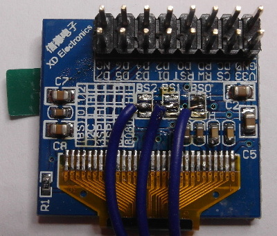
A small table on the left side gives hints about what setting will setup which bus. Typically the busses are:
- 3SPI, 3-wire SPI: Serial Peripheral Interface with three signals: Clock, Data and Chip-Select.
- 4SPI, 4-Wire SPI: Same as 3SPI, but with one additional line for commands and data (often labeled as D/C, RS or A0)
- I2C, IIC or TWI: Inter-Integrated Circuit Bus which has two signals: Clock (SCL) and Data (SDA).
- 8080: A 8-Bit bus which requires 8 data lines, chip select and a write strobe signal.
- 6800: Another 8-Bit bus, but with a different protocol.
At this point of time, it is often a good idea to read the datasheet of the display controller or the manual for your display for instruction on how to setup a specific bus.
Sometimes the bus is just fixed and can not be changed. For this oled with SSD1306 controller nothing can be changed:
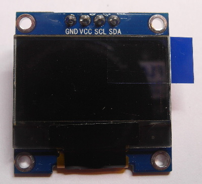
The type of the bus can be guessed from the number of pins and their lables. In this case, it seems to be a I2C bus because of the SCL and SDA lables.
For our initial example the PCB looks like this:
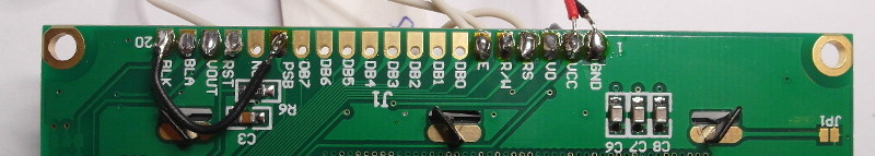
According to the ST7920 datasheet, the PSB pin selects between the 8-Bit and the serial (SPI) bus. For the serial bus, pin "RS" is "Chip-Select", pin "E" will be the clock input and pin "RW" acts as data line.
Note: In the picture, PSB is connected to BLK, which in turn is connected to GND. This will select the serial bus for the ST7920 display.
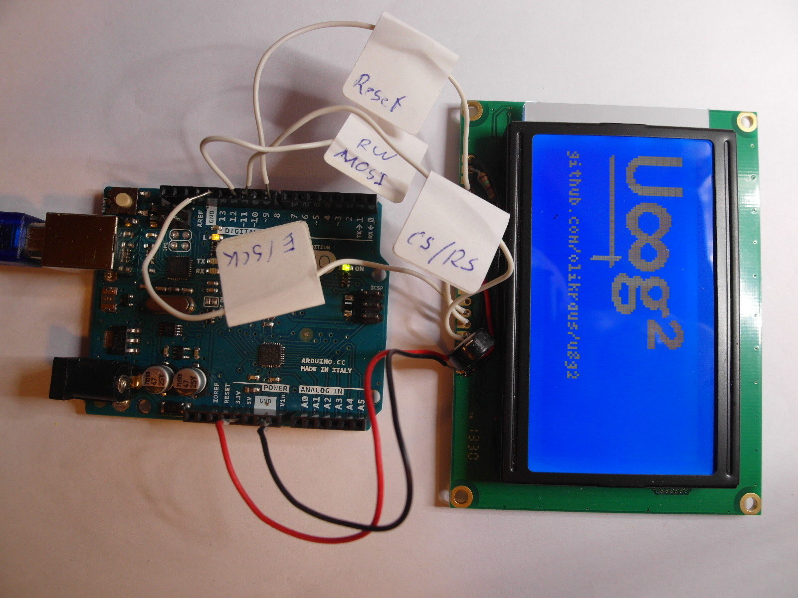
The display must be connected to the Arduino board in order to transfer data from the Arduino board to the display. Depending on the selected physical bus, several pins have to be connected to the outputs of the Arduino board.
In general, U8g2 can use any outputs of your Arduino Board. So it does not matter which output pin is used (However it might be clever to select specific pins for hardware accelerated bus communication).
My suggestion is to write down the wiring. Here is the example for the ST7920 display.
| Display Pin | Arduino Pin Number |
|---|---|
| E, Clock | 13 |
| RW, Data, MOSI | 11 |
| RS, Chip Select | 10 |
| RST, Reset | 8 |
Note: RS (as labled on the PCB) actually means "Register Select", however for SPI mode the RS pin becomes "Chip Select".
Remember to connect PSB pin with GND. Also apply correct voltage to the V0 input for this type of display (see datasheet).
U8g2 needs to know which output pin is connected to which input of the display: The pin numbers are provided as list of arguments to the U8g2 constructor. The position within the list is important and indicates the function/purpose of the pin.
From the table here, the constructor
has the following template (with u8g2 as object name):
U8G2_ST7920_128X64_1_SW_SPI u8g2(rotation, clock, data, cs [, reset])
After something which is called "rotation", the constructor expects the pin number for the clock line, the data line and the chip select line (cs). The reset line can be provided optionally.
The examples include similar constructor calls. You can uncomment one of them and update the pin numbers, if required:
U8G2_ST7920_128X64_1_SW_SPI u8g2(U8G2_R0, 13, 11, 10, 8);
A complete example will look like this:
#include <Arduino.h>
#include <U8g2lib.h>
#include <SPI.h>
#include <Wire.h>

U8G2_ST7920_128X64_1_SW_SPI u8g2(U8G2_R0, 13, 11, 10, 8);

void setup(void) {
  u8g2.begin();
}

void loop(void) {
  u8g2.firstPage();
  do {
    u8g2.setFont(u8g2_font_ncenB14_tr);
    u8g2.drawStr(0,24,"Hello World!");
  } while ( u8g2.nextPage() );
}
U8g2 supports three different drawing modes:
- Full screen buffer mode
- Page mode (This is the U8glib picture loop)
- U8x8, character only mode
- Fast
- All graphics procedures can be used
- Requires a lot of RAM
Use the U8g2 constructor from here. The constructor must include the "F" character. For example:
U8G2_ST7920_128X64_ F _SW_SPI(rotation, clock, data, cs [, reset])
- Clear the buffer with u8g2.clearBuffer().
- Draw something with the usual draw commands.
- Send the buffer to the display with u8g2.sendBuffer().
void setup(void) {
  u8g2.begin();
}

void loop(void) {
  u8g2.clearBuffer();
  u8g2.setFont(u8g2_font_ncenB14_tr);
  u8g2.drawStr(0,20,"Hello World!");
  u8g2.sendBuffer();
}
- All graphics procedures can be used
- Only a little bit of RAM is required
- Slow
Use the U8g2 constructor from here. The constructor must include the "1" or "2" character. For example:
U8G2_ST7920_128X64_ 1 _SW_SPI(rotation, clock, data, cs [, reset])
- Call u8g2.firstPage().
- Start a do-while loop
- Inside the loop-body: Draw something with the usual draw commands.
- Loop as long as u8g2.nextPage() returns true.
Note: Always create the same picture inside the loop body. See details here.
void setup(void) {
  u8g2.begin();
}

void loop(void) {
  u8g2.firstPage();
  do {
    u8g2.setFont(u8g2_font_ncenB14_tr);
    u8g2.drawStr(0,24,"Hello World!");
  } while ( u8g2.nextPage() );
}
- Fast
- No RAM required
- No graphics possible
- Not available for all displays
Use the U8x8 constructor from here. For example:
U8X8_ST7565_EA_DOGM128_4W_SW_SPI u8x8(clock, data, cs, dc [, reset])
All draw commands directly write to the display.
void setup(void) {
  u8x8.begin();
}

void loop(void) {
  u8x8.setFont(u8x8_font_chroma48medium8_r);
  u8x8.drawString(0,1,"Hello World!");
}
![]()