Basic hardware test examples #3324
Conversation
There was a problem hiding this comment.
That was a quick reaction :-)
As mentioned before I like the setup of the Hardware. I would also like to use DUT0 to DUT1 tests for TCP and UDP testing. So they would have to be started at the same time.
Just some minor annotations and suggestions.
Maybe it would be good to test GPIO by directly connecting two pins. That way in case of failure there would not be so many parts involved and troubleshooting would be eased.
Maybe it would make sense to have a HW manager which knows how to set up the HW for certain scenarios.
It knows that it has to set the I/O Expander to open drain if the UART is to be used e.g.
It knows how to connect the GPIOs for GPIO testing and maybe even just gets told to set GPIO 8 to HIGH for testing interrupts.
But that is not part of this PR and might also be overdone.
That way the same test could be run on different hardware where the pins might be connected directly instead of using the expander.
| | GPIO 1 | Primary UART transmit; reserved for host communication | | ||
| +---------+---------------------------------------------------------+ | ||
| | GPIO 2 | [reserved for 1-Wire] | | ||
| | | [+ reserved for 23017 INT[AB] connections] | |
There was a problem hiding this comment.
Will the interupts interfere with 1-Wire or is it robust enough to stay off the line.
There was a problem hiding this comment.
The interrupt pins can be configured into open-drain rather than push-pull, so that should be fine, though the tests will have to remember to do it.
There was a problem hiding this comment.
So that can be done by the test environment library/HW manager
tests/NTest_gpio.lua
Outdated
|
|
||
| local N = require('NTest')("gpio") | ||
|
|
||
| N.test('setup', function() |
There was a problem hiding this comment.
That looks good as an init function. I had thought about adding init_run, before_each_test and the one afterwards to NTest but this makes the init_run and its counterpart obsolete at least.
There was a problem hiding this comment.
I wonder if a N.preflight variant on N.test might still be useful: sometimes if a test fails, there's no point in running any of the rest of them, and so we should just stop now.
There was a problem hiding this comment.
I was planning to have a collection of features which could be required in the test declaration (or the testrun) and a (configuration file)/(detection process for installed modules) which is checked before running a test.
But preflight allows for dynamic checks.
tests/NTest_adc.lua
Outdated
| end | ||
|
|
||
| -- test all four stops on the way up, and the three to come back down | ||
| for i=0,3 do mktest("%d up", i) end |
|
BTW the tests are red (hehe last thing I added in the NTest PR) |
The way I have it wired up right now, DUT1 ends up lingering in RESET until DUT0 releases it, I think. But yes, certainly the plan is to drive both DUTs in tandem and have them flex their networking stacks. Ideally there'd be a series of tests in which both of the DUTs
Not opposed, just somewhat lacking in free pins. Would you be equally happy with a dual-DUT GPIO test? The two UARTs are indeed directly connected and we could do without futzing about with the I2C I/O expander in such a test.
I like the idea of a "nodemcu test environment library" that knows how to do parts of the bringup; that's a solid plan.
Expanding further to a kind of general API for test environments, plural, seems like a worthwhile goal but I'm not sure I quite see how to generalize from the singular test environment I've proposed to more than one. But I certainly wouldn't object to seeing such a thing! |
... ?
That would still require both DUTs to work together. Maybe DUT1 could just implement a short cirquit between the two pins. Just like I plan to just have something similar for the TCP stack. So DUT1 would be as dumb as possible and the entire test logic would run on DUT0.
I would rather use it for developing new tests and not having the complete test HW available i guess. |
I, uh, apparently hit send prematurely, sorry. "... both of the DUTs speak to each other over the network in various ways, including both connected to the same external AP and one STA connected to the other's AP or AP+STA modes."
Fair.
Well, as I said, I'm quite open to suggestion. I think the simplest thing might just be to have a test environment description module which just reports what the peripheral environment / pin wiring / ... looks like, coupled with multiple |
The underlying assertok uses but one msg argument.
Use the hardware defined in the test environment to exercise the ADC
Use the hardware defined in the test environment to exercise some gpio
pins and trigger logic.
|
How about having a WIKI page which describes our road map on this. That way it doesn't get lost in various Issues. |
|
From looking at this, do you need raw ESP8266 modules, or can you build this test environment with (say) a pair of D1 Minis + supporting parts? I could fab a small number of boards to make building the test rig fairly easy..... |
|
Certainly the intention was to be compatible with the DIP carrier boards (e.g., D1 Mini, Feather, &c, but probably not the 8-pin modules, which also just don't have enough I/O for most peripheral testing) to make it easy for anyone to stand up a test environment paralleling the one on my desk so that the bus factor was more than 1. For the same reason I picked an I2C I/O expander available in DIP packaging and would, ideally, continue to rely on breadboard-friendly peripherals for testing. Fabbing some boards eventually would be great, but I think that we have not yet actually converged on what the full test environment looks like (though I hope I've made a good start between what's in tree and what's in my |
|
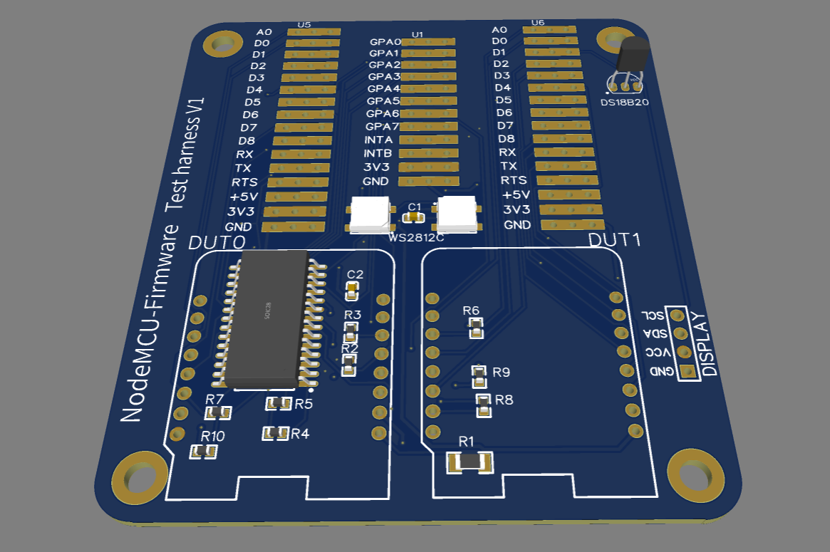
If you create yourself an account at https://easyeda.com and then tell me your username, I can add you to the project. The design holds two D1 Minis, has the MCP23017, a WS2812, a position for a DS18B20 and a position for the cheap 128x64 OLED displays. The cost of these boards is ~$30 for 10 -- this is populated with the MCP23017, the WS2812 and all the resistors. It would need female headers soldering in to hold the D1 minis, and a header for the OLED display if required. If we switched the 23017 to be a PCA9554 (8 port) or PCA9555 (16 port), then that would save $5 -- bringing the cost down to around $25/10 boards (plus shipping). Adding other connections and the like is easy (and remarkably cheap if the component is common). |
|
Hm! That is surprisingly cheap! The 9555 is a little less flexible than the 23017, but I don't think we're likely to miss the missing features. OTOH the 9555 apparently exists in DIP form, but isn't made in it any more? Perhaps there's yet a third option, or perhaps this lends increased weight to @HHHartmann's suggestion that we need a test fixture abstraction library against which the tests are written. ETA: I'm |
|
I'm going to leave it as the 23017 as he pricing on the other parts seems confusing to me.... I added:
Rough idea:
|
|
Oh nice. Some random thoughts:
|
|
Wow that looks good! Not sure if we need that much prototyping area. Maybe the ability to solder some female headers to be able to connect to a breadboard right on both sides of the wemos and the same for the 23017 Also thought about the antenna issue and automated WS2812 tests. Isn't there a 1W color sensor? I was wondering if we could have one DUT run a stable version of the firmware, only adapting the Lua code if needed and only have to flash the other DUT for testing. That way we could probably only connect that one to the computer, powering the whole board from that connection and only occupying one USB port. |
|
Headers in lieu of a prototyping area is probably also fine. I'm not sure about testing via one DUT. It might be possible, but I think at least some of our tests are going to want to update the firmwares on both (e.g., inter-DUT networking tests). I don't believe there's any harm in having two USB cables to hook up, and it should be relatively straightforward to ensure a lack of ground or power loops on the board -- most peripherals connect to just one DUT and so can draw their power and ground links from that. The three cross-DUT links right now all have current limiting resistors and besides the two should be at the same ground anyway given their USB connectors. That said, if there's really a strong reason for only having one USB cable, we could bring DUT1's RESET and GPIO0 over to the 23017 (just as we already bring its TXD, RXD, and WAKE pins) so that DUT0 and the host could conspire to reprogram DUT1 (slowly, by using DUT0 as a bounce buffer and having it juggle its UART pins). That does mean that DUT1 chews up five of the 23017's channels all told, but that might be OK; we still have Paris^WPort A completely free. |
|
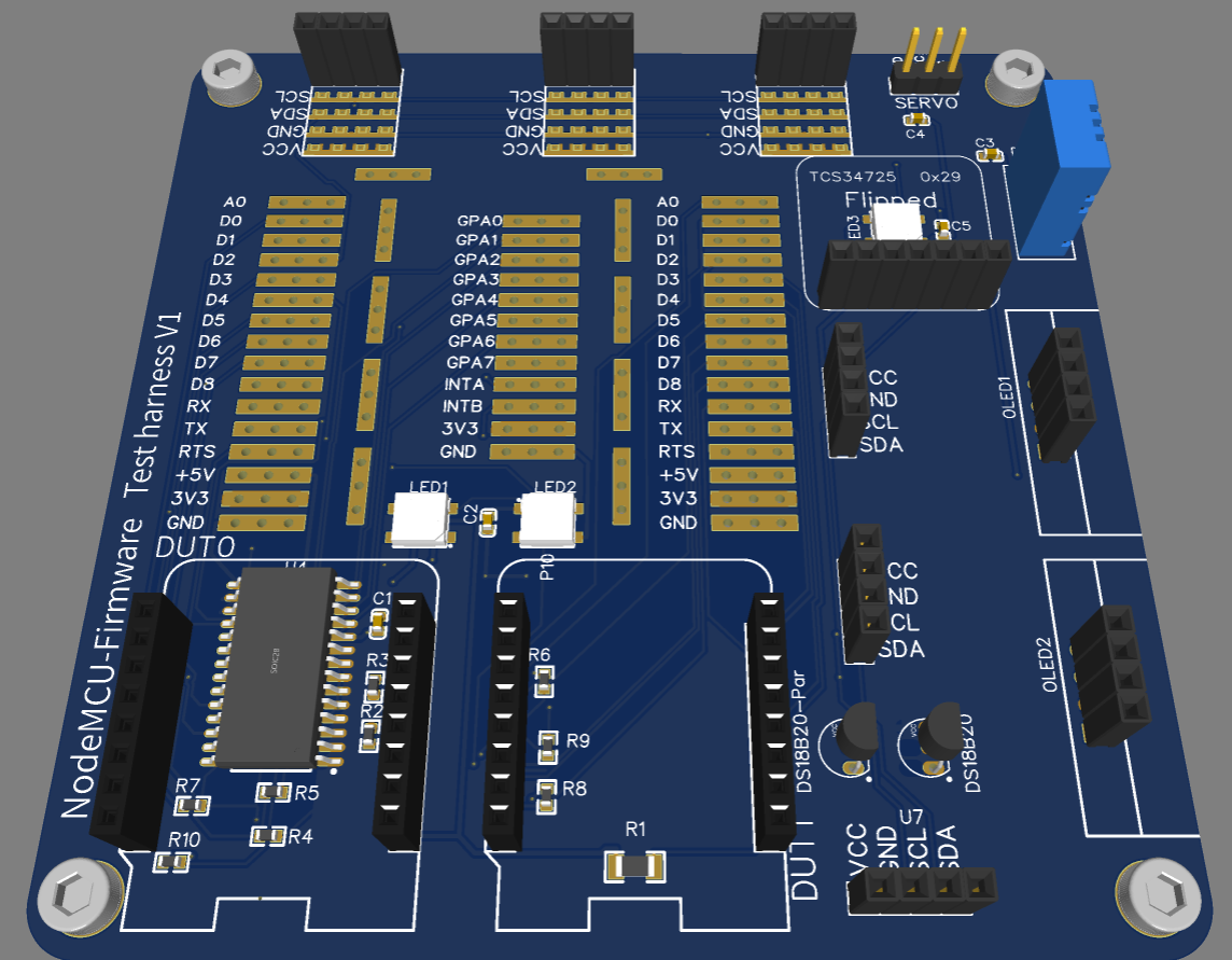
Currently I'm not bringing over the RX/TX pins from DUT1 to DUT0 -- these can't go via the 23017 as it can't emulate a UART.... Also, I guess that we would have to use the software UART to drive them.... The prototyping area just brings out each pin of DUT0 and DUT1. each pin is brought out to three holes on .1" spacing. You can solder a 16 pin 0.1" header down this strip if you want. The 5V rails from the two boards are connected via a 1Ω resistor to prevent large loop currents. The 3.3V rails are entirely disconnected, but should be close as there are identical regulators providing that voltage. I suspect that we could add a TSC34725 board mounted upside down over one of the ws2812s. These boards are cheap.... It would allow verification of the ws2812 driver. I'm also going to add another 3V3, GND, SCL, SDA header (or two) so that random other devices can be attached. E.g. BMP280 etc. It appears that most of the cheap chinese modules have the pins in that order..... |
|
Oh, fooi; I got wires crossed (hah) and was thinking that we already bridge DUT UARTs... and we sort of do, but alternate UART pins, which probably aren't usable by the bootstrap loader (unless someone knows some magic strapping configuration). Maybe we could swap the connections to DUT1 GPIO15/GPIO13 to DUT1 TX/RX, but we'd probably need some way to disable the USB UARTs on DUT1. 👍 on the 1Ω resistor between the 5V rails and the TSC34725 and the extra I2C breakouts. |
|
It isn't quite clear how to cross-wire the UARTs etc. This is the current version of the board. It is somewhat larger -- about 100mm square. It includes spaces for a bunch of I2C devices which can be added or not. There is support for measuring the color of the WS2812 with a light sensor.
|
|
I note that the DUT1 has no connection on its RST pin. This is probably required if we want DUT0 to control it. Also, I suspect that we want to cross wire the alt UART pins on DUT0 to the real UART pins on DUT1. However, You need to pull hard on the DUT1 RX line to override the drive of the USB interface. This implies no resistors in the path. I'm not sure why the existing design has resistors and the 23017 in the path. I've added connections from the 23017 to DUT1_RST and DUT1_D3 (which is GPIO0). |
|
I think we should abandon the idea of DUT0 controlling DUT1 and just use two USB ports on the host. IMHO it's by far simpler that way. The existing two cross connections should be more than sufficient for us to test both The resistors are in the cross-coupling path and in fact should be between all connected pairs of push/pull drivers to prevent buggy software from frying hardware: pushing a strong Vcc into a strong pull to ground is going to cause something to get warm and maybe smoke. |
|
I added the cross linking to the RX and TX on DUT1 -- but it is controlled by a 23017 pin. Normally it is disabled. It is designed so that programming errors will not cause smoke.... Total cost is now $35 for 10 boards + maybe $20 shipping. Any more capability that anybody wants? There is a significant cost increase if the board gets any larger -- it is currently 100mm x 100mm.
|

|
I think I'd rather we all had breadboards for a while before baking the test wiring into PCBs. Obviously others are welcome to other opinions, but I think that hardware has outstripped software at this point and it would be good to actually have tests for more of the things you've mounted on that (very lovely) board. |
|
Time to break out the soldering iron and see how much works...
Philip
…On Sun, Dec 6, 2020, 19:37 Nathaniel Wesley Filardo < ***@***.***> wrote:
***@***.**** commented on this pull request.
------------------------------
In tests/NodeMCU_Test_Environment.rst
<#3324 (comment)>
:
> @@ -0,0 +1,157 @@
+###########################
I loathe Markdown, but if someone commits the conversion I won't be too
upset.
—
You are receiving this because you commented.
Reply to this email directly, view it on GitHub
<#3324 (comment)>,
or unsubscribe
<https://github.com/notifications/unsubscribe-auth/AALQLTODVRLQEYLISQX2EG3STQPU5ANCNFSM4TOMZDDQ>
.
|
Now that
NTesthas landed (hooray) it's time to start fleshing out our test environment. Towards that end, here are example tests ofadcandgpiowhich rely on some modest external hardware, which is also described in this PR. This is a subset of the work done in #2983, so it may feel familiar.devbranch rather than for thereleasebranch.