This project aims to reverse-engineer the hardware design of the Quansheng UV-K5 handheld amateur radio transceiver, specifically focusing on V1.4 of the PCB, which is also used in UV-K5(8) and similar models. The goal was to create a KiCad design that closely resembles the original hardware. Feel free to use this KiCad project to explore more about the mentioned radio or as a starting point for enhancing Quansheng's original design, such as improving RF filtering.
This project is a community effort, and many people have contributed in various ways (e.g., suggesting make and model of previously unidentified hardware components, component measurements, 3D model creation, reviews, hardware donations, etc.). I particularly want to thank Manuel (Manuel's GitHub) for donating the PCB and measuring components, and Ludwich (Ludwich's GitHub) for thorough documentation (including maintaining the wiki) and improving my initial schematic.
Manuel desoldered all components from his PCB after his radio malfunctioned and began measuring them. For components he couldn't measure, he sent them along with his PCB to me.
I measured the remaining components using a nanoVNA, soldering each to a test board to ensure precise measurements.

All documentation is available here: Parts. This resource was invaluable during the reverse engineering process.
While we might have encountered measurement errors and may not have chosen the correct component values every time, overall, I believe we've done a decent job. If you spot an error, please inform Ludwich or me.
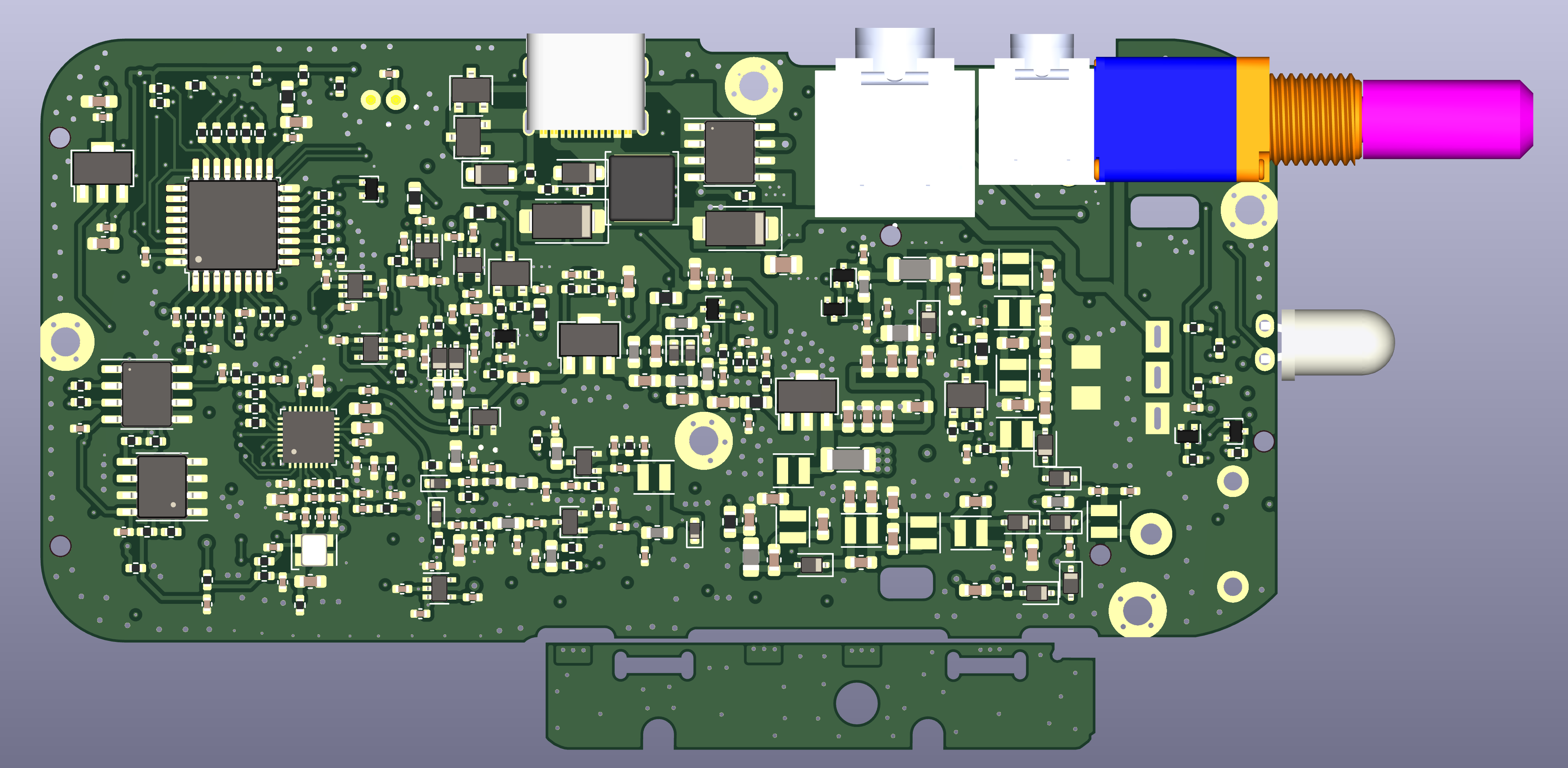
Afterward, I photographed the PCB to obtain high-resolution images. I also sanded down the PCB to expose the two inner layers, documenting the process here: PCB Layer Preparation.

I then processed the layer pictures, imported them into the KiCad PCB editor, and aligned everything as accurately as possible. You can still find these pictures in the PCB editor for reference, contributing to the project's size (approximately 60 MB).
Next came the laborious tasks:
- Setting up the PCB view with all PCB borders
- Selecting a random component on the PCB picture
- Placing it onto the schematic
- Switching to the PCB editor and placing the component
- Checking the 3D view of the PCB
- Linking a 3D model for the component if necessary (a time-consuming task)
- Placing additional components
- Connecting the components in the schematics editor
- Switching to the PCB view, updating it
- Running DRC on the schematics and PCB and correcting gating issues
All of my work was completed over a period of about three months, mostly on weekends.


Q: Why is this design labeled as Rev. 0.9?
A: I'm not completely satisfied with the current schematics' appearance and plan to transition the project to KiCad 8. Consider this a version for public review, and please provide feedback for improvement.
Q: Why wasn't the project set up in KiCad 8 from the beginning?
A: KiCad 8 wasn't available when I started the reverse engineering, and I didn't want to switch mid-way.
Q: The 3D rendering of the PCB is incomplete.
A: Some components lack proper 3D models or have incorrect ones from similar components, causing them to be missing in the PCB's 3D view. If you have .wrl or .stl files to contribute, please let me know.
Q: Why are there many errors when I run DRC on the PCB?
A: This project aims to understand the Quansheng UV-K5 radio's hardware design, not to manufacture PCBs directly. You can't use the PCB files for manufacturing without modifications to meet specific manufacturer rules.
Q: Some PCB tracks aren't routed correctly on the grid.
A: Yes, I'm aware. It was a compromise to complete the project in less time. However, all connections should be accurate.
Q: Why don't the reference designators in this project line up with those in Ludwich's wiki?
A: I chose not to align them to save time.
- C192 in the schematics has a wrong value.
Wrong: 10 nF
Correct: 20 pF