This project was created to solve the need for a MY99 BMW 540i (E39) to be able to brake using the semi-autonomous driving software OPENPILOT.
The software and hardware of this project has been done by fellow that have no knowledge of any kind on automotive, software or hardware developing stuff nor electrical engineering. I just like to get things done. So if some ever implements this, keep in mind that there is some change that the BrakeModule will behave unwantedly or will damage your cars electrical system! If you have better knowledge than I, please contribute on developing this.
This module has been designed for use with a car equipped with the BOSCH ABS 5.7 Dynamic Stability Control system 3 (DSCIII). It is possible that this module could be adapted for use with other cars that use this system, but modifications to the software may be required. The description of the system provided here is based on the author's observations and assumptions, and may not be accurate for all cars that use this system. There might also be a change this could be used on BOSCH 5.3 system, if DSCIII (or similar) is implemented.
List of cars that use BOSCH 5.7 system found on the internet.
| Brand | Model and year | |||
|---|---|---|---|---|
| Acura | RL, 2000-2004 | |||
| Audi | A4, 2000-2004 | A4, 2004-2008 | A6, 1997-2004 | A7, 2001-2005 |
| Audi | A8, 2002-2010 | S4, 2004-2006 | S6, 2002-2003 | RS6, 2003 |
| Alfa Romeo | 148, 2001-2010 | 156, 1997-2005 | 166, 1998-2007 | GT, 2003-2010 |
| Bentley | Continental, 2004-2008 | |||
| BMW | E39, 1995-2003 | E46, 1998-2005 | E38, 1994-2001 | E65 E66, 2001-2011 |
| BMW | E53, 2000-2007 | E52, 2000-2004 | ||
| Citroen | C8, 2002-> | Xsara, 1997-2005 | Xsara Picasso, 1999-2010 | |
| Dodge | Sprinter, 2003-2006 | |||
| Ferrari | F430, 2005 | |||
| Fiat | Stilo, 2001-2008 | Ulysse, 2002-2011 | ||
| Ford | Mondeo, 2000-2007 | |||
| Jaguar | X-type, 2001-2009 | |||
| Lancia | Phedra, 2002-2010 | |||
| Land/Range Rover | 2002-2012 | |||
| Maserati | Quattroporte, 2004-> | |||
| Mercedes-Benz | Sprinter, 1995-2006 | Viano, 2003-> | V-Class, 1996-2003 | |
| Opel/Vauxhall | Vectra, 1998-2001 | |||
| Peugeot | 307, 2000-2008 | 807, 2002-> | ||
| Porsche | 911, 1997-2005 | 996, 2002-2004 | ||
| Renault | Avantime, 2001-2003 | Clio, 1998-2005 | Clio, 2005-2012 | Megane, 2002-2008 |
| Rover | 75, 1999-2005 | |||
| Seat | Cordoba, 2002-2009 | Ibiza, 1999-2002 | ||
| Skoda | Fabia, 1999-2007 | Felicia, 1994-1998 | Superb, 2002-2008 | |
| Saab | 9-3, 1999-2002 | 9-5, 2002-2004 | ||
| Smart | City-Coupe, 1998-2007 | Roadster, 2003-2005 | ||
| Subaru | Outback, 2003-2009 | |||
| Toyota | Avensis, 1997-2003 | Avensis, 2003-2008 | Corolla, 2001-2007 | Verso, 2001-2007 |
| Volkswagen | Passat, 2000-2005 | Phaeton, 2002-> | Polo, 2001-2009 |
Likely there are more, found also these:
- Ford Freestyle
- Honda Civic, Passport, and Pilot
- Lincoln Town Car
- Mercury Grand Marquis and Sable
- Subaru Baja, Forester, Impreza, Legacy
I cannot guarantee the accuracy of this list, and I'm uncertain if all the mentioned cars are compatible or equipped with the necessary charge pump for braking purposes.
The BrakeModule has been designed to receive brake request values from OPENPILOT via the CAN bus. OPENPILOT is an open source driver assistance system that offers Automated Lane Centering and Adaptive Cruise Control for over 200 supported car makes and models. To function properly, OPENPILOT needs to be able to control the longitudinal (gas and brake) and lateral (steering) movements of the car using the CAN bus. For more information, see https://comma.ai/ and https://github.com/commaai/openpilot.
Video introducing OPENPILOT.
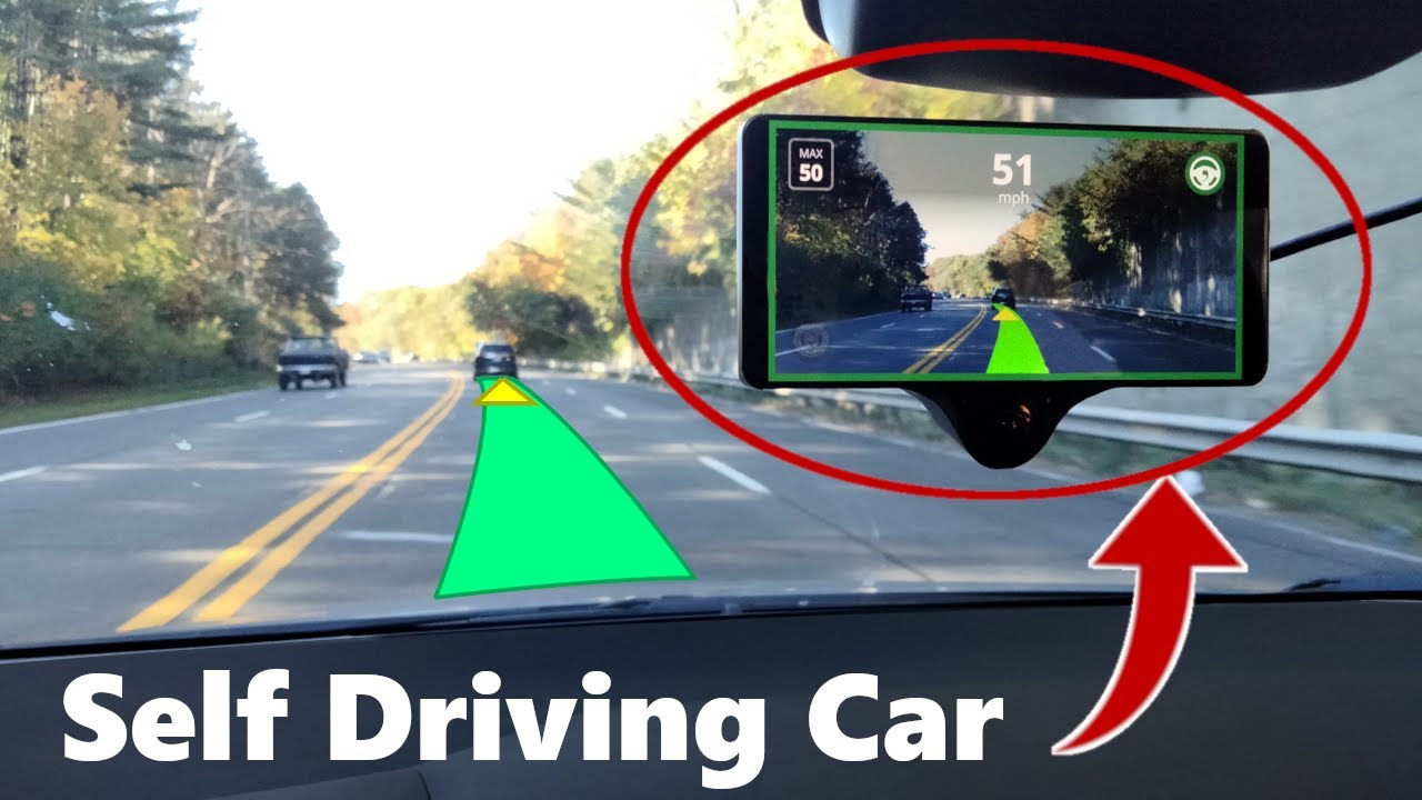
At the moment, my implementation of the OPENPILOT only utilizes vision-based ACC (no radar) with stop and go capability, achieved using the BrakeModule and a device similar to the comma pedal. Lateral control is a work in progress. The top left of the screen shows the set speed of 87 km/h, and the top center shows the current speed as reduced by the vision system that detects the distance, speed, and acceleration/deceleration of the lead car.
Drive.mp4
The following video demonstrates the performance of OPENPILOT and BrakeModule together. The pink graph shows brake pressure in bar, the purple graph shows gas pedal position (controlled by OPENPILOT, not the driver), the blue graph shows car speed in km/h, and the turquoise graph shows the distance to the lead car in meters.
Stop_n_Go.mp4
The system can be roughly divided into few subsystems:
- control module (ECU) that is responsible all of the logic and electrical stuff
- valves that control the brake fluid flow
- ABS relief pump
- charge pump (also known as pre-charge pump)
- sensors that monitor the system and the trajectory of the car.
The ABS module monitors the car's state using its sensors, and determines if ABS or DSC intervention is required. In such cases, the module will generally take the following actions:
- reduce motor torque requesting it via sending CAN messages to the DME (motor ECU)
- relief pressure of individual brakes by controlling the valves and running the ABS relief pump (ABS event).
- apply pressure to individual brakes by controlling the valves and running the charge pump (DSC event).
Picture of BOSCH 5.7 with DSCIII.

By controlling the charge pump, which is responsible for raising brake pressure in the system (10-15 bar), we can also control the car's braking. The charge pump increases brake pressure on both the front and rear axles. Below is snippet from DSC manual that explains how the charge pump control the brakes.

The charge pump is controlled by two N-channel MOSFETs inside the control module, in a half-bridge configuration.
Pic of the 2 FETs inside the module, right one is damaged. These are not the regular type black thingies (type TO-220) that you likely see as MOSFETs.

Handwritten schematic of the driving circuit of the charge pump.

If someone want's to deep dive on Bosch DSC 5.7 ABS Module Diagnosis and Repair read this great post: https://www.bimmerfest.com/threads/bosch-dsc-5-7-abs-module-diagnosis-and-repair.822139/#post-8854110 (the pics are stolen from it).
Further knowledge on how BOSCH 5.7/DSCIII works, look at https://github.com/killinen/BrakeModule/blob/main/dsc_system.pdf in the repo.
Control module/hydraulic unit shown in M54 engine bay.

Charge pump shown in M62TU engine bay.

The concept behind gaining control of the ABS/DSC unit's braking ability is to use a man-in-the-middle tactic (https://en.wikipedia.org/wiki/Man-in-the-middle_attack). This can be achieved by taking control of the charge pump from the ABS module, preventing any diagnostic systems from being confused. To take control of the ABS/DSC unit's braking ability, the following steps can be taken:
- Disconnect the BOSCH control module from the charge pump.
- Reconnect the charge pump wires to a resistor so that the control module "thinks" that the pump is still connected. If the wires are disconnected, the module will throw a charge pump error because it will detect an open circuit via the feedback lines (f/b), shown in handwritten schematic.
- Connecting 12V to the pump and use N-channel power MOSFET to adjust to charge pump load (brake pressure).
- Manipulating the cars brake light (pedal) switch signal wires, as increased brake pressure in the system without detection of the brake pedal being pressed will cause a brake pressure sensor defekt error.
- The BrakeModule determines its operations by reading messages from the car's CAN bus, where OPENPILOT is also connected.
Main principle of driving charge pump and brakelight switch with BrakeModule.

Brake light switch has 4 wires: 12V, ground, signal LOW, signal 2 HIGH. Signal LOW is grounded and signal HIGH is floating when pedal not pressed. When pedal is pressed, signal LOW is floating and signal HIGH is connected to 12V. Those lines are in BMW lingo S_BLS (brake-light switch) S_BLTS (brake-light test switch).

In E39 the DME control unit evaluates the signals for the purpose of registering brake operation. The brake-light switch connects to earth (B-), the brake-light test switch connects to B+. And uses this truth table for operation:

The BrakeModule (as well OPENPILOT) is connected to BMW's CAN bus which have following modules attached:
- Instrument Cluster
- LEW (steering angle sensor)
- DSCIII (BOSCH ABS control module)
- DME (engine control module)
Whole bus topology of my car:

The CAN bus used here, should NOT be confused to diagnostic bus which is exposed in OBD ports.
The BrakeModule has three main functionalities:
- Three relays that switch the charge pump in line with the DSC system or the BrakeModule.
- A power MOSFET that controls the charge pump.
- A temperature measurement system to monitor the power MOSFET temperature, along with a FAN to cool it down.
Additionally, the BrakeModule uses a CAN module for communication and a voltage divider to measure the DSC+ line voltage and the car's brake light switch.
The board size is 110x82mm and it contains.
- Blue Pill development board containing STM32F103 MCU.
- MCP2551 high-speed CAN protocol controller bus interface module for commucation.
- 3 SMIH-12VDC-SL-C relays for switching the charge pump in/offline.
- TC1413N DIP8 mosfet driver.
- POWERPAK SO-8L MOSFET.
- 12V to 5V buck converter module.
- BS250P for driving the brakelight switch high side.
- HK19F-DC12V-SHG relay for driving the brakelight switch low side.
- TMP36 temperature sensor for MOSFET.
- SOT23-NPN transistors for common switching purposes, eg. possible fan.
- TO92-NPN transistors for driving the SMIH-12VDC-SL-C relays
- USB to UART (FTDI) connector for updating the software and debugging.
- Voltage dividers for sensing brake pedal high side (S_BLTS) and DSC charge pump driver state (is voltage fed to CP via DSC).
Picture of PCB of BrakeModule v0.3.2.

Picture of BrakeModule inside 3D-printed case.

The software has been developed for the STM32F103 chip using the Arduino IDE, with some STM32Cube HAL functionality added.
Normally he charge pump is connected to the BOSCH control module, with the relays in the normally-closed mode. However, when a braking demand is detected in the 0x343 CAN message (BRK_CMD) from OPENPILOT, the BOSCH module is disconnected from the pump and the pump is instead controlled by a 15 kHz PWM signal from the power MOSFET, with the relays switched to the OFF position from the normally-closed mode. Additionally, the brake light signal lines are driven to produce correct HIGH (S_BLTS) and LOW (S_BLS) signals, indicating to the car that the brake pedal has been pressed. When BRK_CMD demand is no longer detected, first 12V line and ground (PWR MOSFET) will be disconnected from the pump and after 600 ms BOSCH control module is switch back inline with the pump. Also brake light switch is turned OFF. This delay is because if the transition from pump activated with BrakeModule back to DSC module is too fast, BOSCH module will give error code. I think this is caused of pump still rotating (generating voltage to pump wires) and you will connect the pump to BOSCH module, modules feedback lines detects voltage at the pump when it shouldn't and gives an error or brake pressure is seen in brake circuit and brake light switch is turned off.
The speed value (car_speed) is read from message 0x153 and sent to OPENPILOT as the ACC set speed when OPENPILOT is engaged (set_speed).
The brake pedal state determined by reading voltage from the brake light switch HIGH signal line (S_BLTS), and when there is no braking demand in message 0x343 (BRK_CMD) from OPENPILOT, an active brake pedal pressed state (BRK_ST_OP) is sent to OPENPILOT in order to disengage it. The BMW cruise control button presses (BTN_CMD) are detected on message 0x329. If BTN_CMD contains a RESUME button press, it will engage or disengage OPENPILOT's ACC depending on its current state. BTN_CMD also includes cruise controls + and - button presses, which adjust the set speed of OPENPILOT's ACC accordingly when pressed. The BMW's cruise control state (OCC) is detected on 0x545, and if it is on, OPENPILOT will not engage to prevent the original CC and OPENPILOT from simultaneously controlling the longitudinal direction.
The BrakeModule is used to simulate the cruise control system of a TOYOTA Corolla because the OPENPILOT fork identifies the car as a TOYOTA. As a result, data is sent in 0x1D2 and 0x1D3 CAN messages to OPENPILOT, which are typically used by the cruise control system of TOYOTA vehicles. The use of TOYOTA in OPENPILOT is due to legacy reasons, as the first person to use OPENPILOT on an older car implemented it on a TOYOTA Celica. My code is simply a revised version of that original implementation.
If DEBUG is #defined in software you can control the board via serial (look at the readSerial() function) + some debugging messages are shown.
If FAN_CTRL is #defined in the software and the temperature measured by the TMP36 sensor (not implemented in the v0.3 code) exceeds 45 degrees, a small NPN transistor is pulled low, which is connected to the FAN connector (designed to cool the MOSFET). Additionally, if the temperature exceeds 80 degrees, the BrakeModule will disable OPENPILOT and prevent it from engaging until the temperature falls below that threshold (this shabang might is not necessary at least haven't been for me).
Some of the decoded CAN messages that is on E39 CAN bus can be found here: https://github.com/killinen/opendbc/blob/master/BMW_E39.dbc (I'm sure this is not perfect, would be cool if someone else would like to look into it). It is in openDBC format, here's couple good reads what DBC is. https://github.com/stefanhoelzl/CANpy/blob/master/docs/DBC_Specification.md http://socialledge.com/sjsu/index.php/DBC_Format. Great insipiration for reverse engineering the CAN messages was this thread relating to E46 CAN bus messages: https://www.bimmerforums.com/forum/showthread.php?1887229-E46-Can-bus-project. Also for some other chassis CAN msgs see dzid's issue #1. Python library for en/decoding DBC's https://cantools.readthedocs.io/en/latest/.
If I have the inspiration to make of BM v0.3.3 I would:
- Fix HW bugs (funny I found few).
Reduce part count (simplify).- Get rid of extra DSC voltage divider circuit in the upper right corner of PCB (useless).
- Maybe add (working) brake light switch low side sensing (redundancy).
Maybe 4 layer PCB design (could lower the power tracing resistance?)Maybe use of different kind of power MOSFET (is the footprint right).
Follow up to above: Ditch (partly) the 0.3.3 went for 0.3.4 where the design changes will include:
- Safety related HW (this just went overkill but going to test stuff and probably will revert some stuff later on)
- Integrate Panda, steering angle sensor (connects to cars CAN bus) and StepperServoCAN wirings
- Do some simplifying and part changes
- Add testing points for easier development
- Add brownout detection
- Add few new HW bugs
It may be possible to ditch the pump-side relays and use a similar MOSFET configuration as in the DSC module. This would allow the system to sense the DSC wires and drive the pump accordingly. The below picture shows the voltage in millivolts (DSC_VOLTAGE) measured from the DSC+ wire. There appears to be some sort of bootstrapping cycle, and the voltage is increased when the pump is running and driven by the BrakeModule. The running of the pump can be observed from the PWM value (2047 = 100% duty cycle), and the brake pressure (in bars) is shown for reference. The pressure reading without the pump being driven is the result of me pressing the brake pedal :)

The unfortunate thing in these voltage spikes are IMO that if you would like to eliminate the change of charge pump not running when DSC module is demanding it but BrakeModule controlling the pump it will result of somewhat of an lag if you are waiting to see that is this voltage spike bootstrapping cycle or an real pump control demand. Will this result an real world meaningful lag, I can't really say (this doesn't affect only w v0.4 but current system also).
Benefits for this hardware design would be reduced complexity and part count. This is likely to result in simpler software as well. Relays switching noise should be reduced. Overall these are quite minor improvements.
In older HW v0.2 I have used (tested) relay or N-channel MOSFET for controlling the LOW side BLS signal line (S_BLS). I somehow prefer the use of NC-relay, but maybe transfer to some other type of solution in the future. Dual channel MOSFET IC maybe or something.
What I have understand there are standards and guidelines for automotive hardware and software design, this project does not follow any of those.
My main concern is that if a stability control event occurs while the BrakeModule is controlling the charge pump, there is a non-trivial chance that the stability control system will not function as intended. I have not yet experienced any problems with this, but I understand that more testing is needed to be confident that this will not happen. I plan to conduct further testing to address this concern in the future.
If the ABS control unit is damaged, it can be difficult and costly to repair. I cannot guarantee that using the BrakeModule will not cause any damage, but so far, I have not experienced any problems with my unit, even though it has had quite a bit of rough love. This the quality of the German engineering ;)
I am not aware of the maximum capabilities of the charge pump, such as whether it can overheat and brake if run for too long. The software does not have any restrictions in place to prevent this. I have run the charge pump for extended periods in red lights in Nordic summer (best outside 25-30°C), and so far it has not failed. However, on hotter days, I have observed a decrease in the maximum brake pressure that the pump can produce, which I assume is due to the brake fluid getting hot.
If brake pedal is pressed hard and BrakeModule is controlling the pump and switched back to "normal mode", BOSCH module will give an error (this might be solved).
A well-designed approach to installing the module would likely involve using a professional case to protect the components and provide integrated heat dispersion. This would prevent the components from being exposed and improve the overall performance and reliability of the system.
That wouldn't it be best if you could control the BOSCH control module using CAN to access the charge pump, but I do not have the knowledge or expertise to do so. This approach may be feasible because the same unit is used with ACC systems, and the only way that I can imagine to apply the brakes is to use the charge pump.
The benefits in my mind of the BrakeModule to latter is to have full control of braking (my understanding is that OEM system won't brake below certain speed in ACC mode). Scalability is also benefit because you probably won't need to reverse engineer all the possible messages/programs that are implemented on different car brands and models. And lastly this is more fun :)