
An open-source robot arm
PURPOSE: to design a robot arm using bio-inspiration for higher modularity and higher loads than leading commercial designs in 2023.
| Github Repo | Website |
If an expert reviews this project, they will find numerous imperfections; potentially laughable ones. A well-trained mechanical engineer would not release such imperfections. But this project is not a release, just as every script posted in open software is not a final working script. We are pursuing a new paradigm, where open hardware ascends to match open software. In software, open development has surpassed privatized development. Developers discovered by publishing every step in realtime, we gain the world's contribution at every step, and 10,000 brilliant minds can outperform a well-paid team of 10 minds. The only way to reach the new paradigm is to opensource the full development process, not only the end result. So, we start the project with a goal and NOT with a build, and we trust experts to see the possibilities instead of the present status. Then, we can incite the collaboration necessary to achieve the impossible.
There is no intention to reproduce a result that has existed before, so the result cannot be bought. There is no deadline. The prerequisite to completion is expertise, not funding or parts or tools.
Version 1
- Bio-inspired - having damping forces and torque relationships similar to a human arm.
- Digital-twin oriented - the simulated design shall represent the real implementation sufficiently to simulate motion.
- Parametric design - the geometry leaves space for variations and modifications of internals & frame.
- Having no encoders required *️⃣
An initial builds should aim for low cost, usually achieved with 3D Printable + OTS parts. It should serve to validate dynamics models, test feedback control functions, establish parameters for further development. Ie, instead of aiming for a torque at a joint, we derive a dynamic function that better relates to the capability of end-effector. A system using DC motors, M2 Belts, and M2 pulleys like those of 3D printers is likely to serve the purpose of a first build. A 1-kg payload target is well-matched to this hardware.
| Biological Sketch | Biological sketch with motors identified | Robot Arm concept with motors |
|---|---|---|
 |
 |
 |
- Derived from SCARA configuration to enhance payload
- Hope to derive encoder-like function of Motor "n" from measurement of reaction torque at motor "n-1"
- All motor assemblies to be backdrivable
- Modular - multi-DOF, selectable
- Parametric - change the size as you wish
- Rigid frame - components will not have intentional compliance or antagonistic actuators
The rules of a bio-inspired robot arm design:
- No arm is fixed to the ground.
- Every arm has a power supply.
- Everything which has an arm, has learning.
- Arms function without knowing the position of the feet.
- Joints have limited rotation angles.
- Every mass in an arm can contribute to a counterbalancing effort for motion.
- Linear motion takes place in pairs of links.
- The actuator of a joint is located in a superior link.
- Structure supports static loads. Actuators support dynamic loads.
- Force is never exerted with just one actuator.
5.1) * Rotation limit is set by tendons, which add strength & spring behavior.
2023.11.14
Extreme precision will be engineered at low cost. How?

Extreme precision at low cost: Expensive modern arms range have a massive waste in design effort, demanding intensive precision from a mechanical team and only subsequently passing the system to a software team. The goal of precision is at the end-effector, nowhere else. Modern industrial robots cost so much because they mechanically solve a problem that should be solved computationally. Each joint is built with extremely fine tolerances, which stack up so that the 1mm movement at the wrist requires a 0.01mm precision at the shoulder. In contrast, a human being tying a fishing knot requires sub-milimeter precision while the elbow is free to deviate broadly. This is the right way.
As Elon once said "Engineers are extremely good at optimizing solutions that shouldn't exist in the first place." Designers have already solved 1mm accuracy at 100 meters lever arm length, for 20 USD. You'll find in a product such as a firearm laser pointer, small knobs that make such a fine adjustment. A $5 servo is capable of controlling these knobs. Combining them is not difficult. The rule here is that OpenArm elements will not be given precision and high-effort engineering in achieving what is already designed and available for purchase. At each moment that we stumble on a goal requiring very high effort, we will ask if that goal serves the robot function or if it simply serves to help with another goal. By this question, we can biforcate between the useful from the useless targets, and design only useful modules.
This arm is intended for learning & feedback. Instead of encoders and highly precise motion at every joint, the end-effector works like a person controls her hands. We have a general sense of our elbow location but we don't perform fine control of the elbow to position the hands finely.
Kinematics will not drive the design. Rather, the motors, back-EMF, counterbalances, will cross-influence each joint. The bot is intended to evolve its performance through AI training (simulated and real-world).
The rigidity will be sufficient to perform simulations and learning without physical prototype, but less rigid than modern COTS arms. Modern COTS designs always have a rigidity intended to meet the resolution of the kinematics equations. Instead, low-force motion planning will be kinematically true but high-force or high-acceleration motion will be controlled through learning, and will not be possible without learning.
*️⃣ As noted above, no encoders required but some measurement of torque or current or derivatives thereof will become part of the control loop in time.
| State of the Art | Benchtop Arm | How the Robot Feels |
|---|---|---|
 |
 |
 |
| Privileged human (with 2 arms & mobile power-supply), sets robot (one arm and fixed power supply). 🎓7 | Heavy Rigid fixture is required to counteract reaction forces. | A human with one arm and feet strapped down. |
If you search high and low for mobile manipulators, the arms can lift only a fraction of the base's capability
| State of the art | How the Robot Feels |
|---|---|
 |
 |
| mobile base capable of 15kg payload, with arm of 2.2kg payload 🎓8 | Competitor in Atlas Stones bodybuilding with a yoga ball |
A concept for method of achieving motion control without encoders or extreme rigidity:
- Stage 1) overhead camera captures fine motion resolution while all actuators sweep all command states + responses. (Encoders could be implemented or not) Dump all data into a model. Derive relationships between control inputs and motion outputs.
- Stage 1 step 2) Also derive a set of relationships between the wrist motion and current generated by elbow being back-driven by reaction torque.
- Stage 1 step 3)Derive it again for all 360 degrees of starting positions. Repeat for all joints relative to all other joints. (Note: this is also what an infant human baby does).
- Stage 2) use the math relationships from stage 1 on a robot with no encoders and no overhead camera to command actuators. Moving from “home” to any fixed position could be achieved within 5 degrees for each joint. With this method, move the wrist near a flower of known position relative to “home.”
- Stage 2 step 2) activate a low resolution wrist-mounted camera to adjust wrist and fingers, along with simple kinematics and known models, to pluck a pedal.
(2023.10.18)
What if the robot can design itself for each application? I almost forgot to disclose this part of the discussion: Multidisciplinary Design Optimization, or MDO for short, is a recent field in engineering that leverages computational power to co-optimize systems with interacting subsystems. In a robot, some systems are power, mass, articulation, rigidity, among other aspects that can have severe tradeoffs when optimized independently. For complex systems, an expert may find a great solution to optimize one aspect but is not fully aware of it's cross-interactions on other aspects. One solution is to create a computer model which combines other models.
In 2015 I took an amazing MDO course in the mechanical engineering department taught by Dr. Douglas Allaire at Texas A&M. This subject was so inspiring that it became core to my masters' thesis. The approach of mathematically optimizing a system of systems takes a great deal of pre-calculation but there is one magical outcome: After building the optimizer, we can adjust the constraints or the application for which our system is intended, and it will re-compute the optimal design. Imagine selecting the best components for your new gaming PC build, for the overall best price and best metrics that you ask for. Then, use the same optimizer to re-select parts for your colleagues CAD workstation. This approach is a perfect pairing for a design like OpenArm and SCUTTLE which are highly modular and intended for broad applications.
After some progress is made, it will make sense to build an MDO solver around the OpenArm, and SCUTTLE, and perhaps the combination of the two.
Ten years of pondering and working with robot arms, and CLICK! We can make them much better, and vastly less expensive. Less rigid materials, less torque-intensive motors, and less fine control. Here are some thoughts that came before the sketches.
<iframe width="640" height="360" src="https://www.youtube.com/embed/5sXRnYCKep4" title="Human-inspired & Bio-inspired concepts NOT found in state of the art Robots" frameborder="0" allow="accelerometer; autoplay; clipboard-write; encrypted-media; gyroscope; picture-in-picture; web-share" allowfullscreen></iframe>Energy regeneration is possible if we use DC motors rather than stepper motors. A DC motor design is quite unique for a robot arm. Usually stepper motors are used, except for extremely expensive encoded servos motors.
The main purpose is NOT to recharge the battery! It is to A) make voltage and current available during transient states while motors work in tandem. B) to generate current in each actuator while other actuators move, giving a measurable parameter for realtime feedback.
Elaborating on realtime feedback: when we move the elbow, the shoulder feels* a reaction. We can (in robot) generate a current in the shoulder motor that communicates the elbow motion, and it also dampens the elbow motion. Taking control of the "braking" force as a variable, we can adjust the damping and control the power returned for a given elbow motion. When the hand grips a mass, we can recompute the desired damping in realtime and maintain the dynamic response of the whole system, or manipulate it. When a tennis plater strikes a backhand, the right (forward arm) tricep transitions from pulling to releasing, allowing the arm to swing behind the shoulder (no braking). When you shift a transmition lever into park, the tricep behavior is much differnt although the wrist is controlling the kinematics. These different dynamics can be implemented through full control of reaction forces. Poewr generation will naturally be a function of reaction forces.
My first question: can energy regeneration be implemented with affordable OTS brushless motors? If so, brushless outperforms brushed DC motors and is the way to go.
On Youtube, Oren made a detailed analysis of recharging batteries on a brushless powered skateboard (📖5) . The video is here. From my calculations, the best-case recharging trial recovered nearly 30% of spent energy. Power was spent during an uphill drive and recovered by braking during during the downhill return.
| Data for Analysis | Chart: Key Takeaway |
|---|---|
 |
 |
In biology, ligaments attach bone to bone, and tendons attach bone to muscle or otherwise serve mobility 🎓8. As of 2023.07, it's undecided whether to design with rigidity for attachments of motors and joints to the structure. If the robot is given hard mechanical stops, it creates discrete discontinuities in the mobility and would be nonoptimal for machine learning. If we introduce endstops that are elastic, then two benefits arrive: First, the end-stop behavior is continuous, and second, extra strength can assist the actuators near the limits. (If you spread your arms and walk through a doorway, you can put a force on the door frame without using your pectoral muscles - that's the tendons helping you exert force for free - instead of using your own energy, you use a "spring force" which simply conservation of energy. You recover your energy from the walking motion and load that into the spring which is in your shoulder.
Implementation of rubber, silicone, or actual springs are worth considering throughout the design. Muscle/bone attachment may manifest in the form of rubber pulleys instead of gears in the geartrain. Rotation-limiting elastic would do a similar job to tendons at the end-stop configurations.
Analysis 06.26:
This analysis compares a battery-recharging test with my data from a Li-ion cell (similar curves) to estimate percentages. Data from a discharge of Li-ion cell from 4.12v starting, no-load voltage is compared with Oren's data from a LiPo cell from 4.18v starting, no-load voltage. Oren's batteries lost 5% of 4.12v at hilltop, giving 3.98v. ��To gather energy data, I found the corresponding 95% of my Li-ion cell starting voltage, giving 0.95 * 4.12 = 3.91v. At this voltage, my cell's energy consumption was 27% of capacity. (capacity, assuming 3.0v equals 0% capacity and 4.12v = 100% capacity, taken from true samples of mWh discharged). The energy level in WH was noted from the corresponding sample, giving 27% energy reduction.��The same method was used to trace Oren's 96% voltage value back to it's coresponding energy level and we see the difference between these samples show 72% energy recovery. 72% of the lost energy was still available at the recovery voltage. The energy loss from 95 to 94% voltage represents more than 70% of the energy loss from 100 to 94% voltage, due to nonlinearity of the Li-ion and LiPo chemistry.
I found a benchmark on-hand so I went ahead and disassembled my Craftsman utility jack which contains a slip ring. They don't make it anymore but this design has LED's that spin with the plate where the jack lifts the car (crazy, right?)
| Slip Ring Base | LED Panel | Contacts | Insulating Polymer | Working LED's |
|---|---|---|---|---|
 |
 |
 |
 |
 |
Takeaways 06.30
- This system lasted for 10 years! I think that's a successful design to benchmark.
- The slip ring probably only carries a few miliamps. It's unclear if the same setup could be used to power motors with 5-10 amps.
- The gaps are maintained fairly tightly (probably +/- 0.2mm) under operation, and the spring-backed contacts do a fine job of maintaining contact when the ring is spun.
- The threaded cap is made from copper or brass, coated with chrome. It carries the ground path back to the jack from the LED panel. The chrome was delaminating, but the copper worked fine after.
- This system carries up to 1 ton and can still rotate under load. However, there's a lot of friction: sliding action between the plastic film and the steel is the only way it spins.
- The electrical contacts consist of steel-on-steel or steel pins on whatever material is shown in the 2nd image. Again there's a tradeoff of wear-resistance versus conductivity.
April 4
AI has been available in search engines for several months now. That's progress. It means that all mechanical engineers just doubled their effectiveness in writing software (using the new tools). It means designers in each discipline are twice as capable to gain understanding in a new discipline (with easier online explanations). And, it means hundreds of design teams around the world have realized they set their reach-targets too low in their planning stages in 2023. This project dream just became half as lofty as it was in 2023.
A discussion of sensors: It will aid this project if we use new terminology. In the definitions below, I added the word "feel." In robotics, I've not found an equivalent term yet. Consider an apple in your hand. You can feel the apple is there. The outreached arm "feels" the apple, measured in the tension of the shoulder. To reproduce this in robots, traditional engineers place a torque sensor at the shoulder. Next, rest your elbow on a desk. It is no longer possible to use the shoulder sensor to sense the apple. The human adjusts her attention to the wrist. Chasing this capability in a robot, we then add a torque sensor at the wrist. If you modify the situation again, we stack up more and more sensors and cost. Next, double the weight of the apple. The robot with lots of sensors still cannot measure if it has two apples or one large apple. As we develop solutions for a robot arm, "sense" can describe active collection of a datapoint while "feel" can describe the more general effort of deriving a useful parameter. We can sense the weight of a clasped object or we can "feel" the weight by running a motion cycle and extracting a mass value from a delta in inertia. We sense the size of an object with one eye and we feel it's distance by comparing info from our binocular vision. We sense
Yesterday I had the pleasure of meeting Dr. David Surovik, employee 11 of Boston Dynamics' AI Institute. He's actually a family member of a Texan friend of mine. This type of interaction (frequent, short meetings with deep experts) is critical, as robotics evolves so quickly. Sometimes it evolves backwards, so we need to interact to avoid local minima.
My key "download" was basically the state of the art for robotics AI - there are some very ethical, good, hardworking people in the leading companies and the biggest question is regarding direction (what do we work on for the 5-year goal?) but everyone is doing their best. I'm pleased to say there's nothing I learned that refutes the direction I'm establishing with OpenArm and SCUTTLE - that's great news.
I've unburied my 2016 masters' thesis on Multidisciplinary Design Optimization of a Cubesat - an essential step in my understanding of how we will make robotics that evolve over time, and advance towards optimality.
You can find the video and a thoughtful description here in the youtube video:
Getting Started
This deisgn will take a long time unless it becomes funded. Collaboration is encouraged. Editing this repository is welcome. Sharing comments & intellectual additions are encouraged by all.
Here are some early open design files.
| GrabCAD model of the first parts of the collar | GrabCAD OpenArm |
|---|---|
| Photo album to share & collaborate | Google Photo Album |
June 2023
June 20
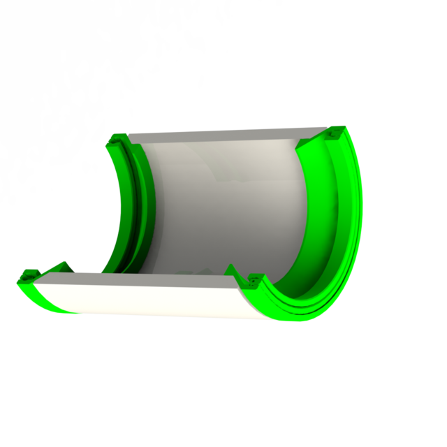
| Bearing loading with bb's, 4.5mm | Bearing on PVC, 60mm | Building Collars |
|---|---|---|
 |
 |
 |
June 24
| early CAD model | gluing with PVC/ABS glue | Bearing tests 60mm & 89mm |
|---|---|---|
 |
 |
 |
June 25
| Steel balls, 9.5mm | Nylong Balls, 11.6mm | New CAD model - better parametrics |
|---|---|---|
 |
 |
 |
The latest bearing uses these nylon balls from Amazon.com link here
Here's a video testing out the bearing after printing:
<iframe width="640" height="360" src="https://www.youtube.com/embed/g5g48a-ZDeI" title="3D Printed Bearing with Nylon Balls" frameborder="0" allow="accelerometer; autoplay; clipboard-write; encrypted-media; gyroscope; picture-in-picture; web-share" allowfullscreen></iframe>June 17: I am beginning modular design elements according with our "rules" and inviting the open community to collaborate. Researchers, Makers, & Hackers Invited.
| Bearing, affordable & printable | Collar cross-section | Early conceptual sketch |
|---|---|---|
 |
 |
 |
October 15
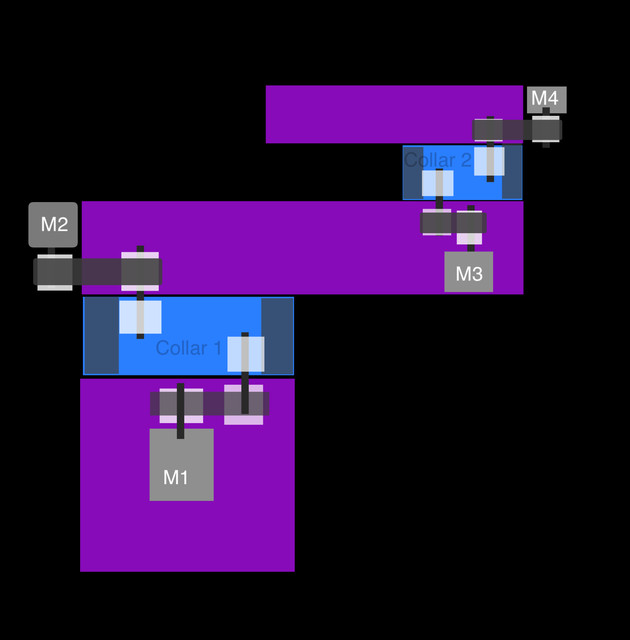
| Prototype 2DOF | Prototype 2DOF |
|---|---|
 ) ) |
 |
This assembly moves nicely - now, deciding on the bearings and the motors will depend on the lifting task we wish to perform. We can give more diameter to the members for greater rigidity, or make it light and fast.
October 20
| Quick Render | Motor Dimensions |
|---|---|
 |
 |
Myself and collaborators went ahead and ordered a brushless motor to test integration. This does not preclude us from using steppers or DC brushed motors later. This month's challenge will be to look for the most elegant integration that leaves us with a parametric assembly. Let's tie in these motors in such a way that changing motors will not pin down the design to one geometry.
Unidirectional By accident, we picked a controller (usually for RC planes) which spins only one direction. At first it was a mistake - now I am on a thinking path about keeping it. Your bicep only actuates in one direction. Maybe that's a clever way to design a robot as well! Later I can discuss how this could be an advantage.
| Github Repo | Website |
Most robot arms have missed the point of arms, and we should improve on this.
| Key Point | Our current robot arms: | How God Designs arms: |
|---|---|---|
| 1 | One design = one product | Make one design with many derivative instantiations |
| 2 | Energy is unlimited, and plugged in | Energy is portable, arms are portable |
| 3 | Base receives high reaction forces. | Base sees no reaction forces OR reaction force contributes to the motion |
| 4 | Base must be rigidly secured. | Base may move. |
| 5 | Has rare materials like aircraft-aluminum | Has common materials like hydrocarbons. 🎓 3 |
| 6 | Components cost is imbalanced: Muscles > Joints > members |
Components cost is balanced: muscles = joints = members |
| 7 | Each joint receives independent control. | Joints are controlled together. |
- Building: I could use builders in parallel or in series - plenty of mistakes will need resolutions. You may build an early revision that becomes overwritten but I guarantee you won't build anything without learning. I will be building this project one module at a time. Then we will need to resize it for various budgets or tasks.
- Design decisions: how much counterweight to add behind each joint? where to place the counterweight? Which parameters to build into the components vs build into the assemblies? (does a long arm need just a longer member or a whole configuration of the assembly? How can we input materials to keep the local center of gravity in the centerline of each joint?
- Modeling: Lots of modeling to do. We can collaborate in solidworks or begin the equivalent designs in Fusion360 or other popular software. We want this design to be as open and repeatable as possible so multiple formats are desired.
- Which nominal belts and pulleys are best suited, to leave space for increasing and decreasing the scale of the arm? Are there kits to be bought in sets that have a high value, such as 3D printer actuators?
- Energy regeneration is important. How can we select a motor type which balances high performance with useful regeneration? This video from Oren's Projects on youtube shows that energy regeneration for common brushless motors is negligible when measured in voltage. But, we need to measure in energy. Do we need to stay with bipolar DC motors in order for energy to return during backdriving?
- Our starting point is a 12v dc motor from the SCUTTLE robot. It's a gearmotor - but which is the best choice for a base publication? How will we route the wires through each member? Should we make a variation of the bearings that have a slip ring? can we prototype a bearing that has a slip ring functioning?
- Are there some off-the-shelf motor driver arrays from another application (like 3d printers, but for DC motors) that have a low-low cost?
- Is it possible to plan for both DC and Stepper motors simultaneously? How big of an electrical mess is made if we backdrive the stepper motors?
- What standard OTS boards should the mechanical team make space for interior to the joints and members?
- Can the whole robot communicate with i2c? Do we need somethign more robust like CAN-bus?
- We wish to recapture energy (even tiny amounts) when the small arm swings and backdrives the larger member. how can we switch responsively between motor driving, motor breaking, and energy recap?
- Note: the purpose of energy recapture isn't to try to conserve all energy, it's to maintain in our models that the consumption will vary based on this - and gain understanding of the interactions so they can be modeled.
- which are the first models necessary to begin simulation? what parameters do we need to output to help the simulation team operate effectively? Are there some university or research courses currently operating on digital plans that we could offer this design to? That's a win-win, then they could align their digital simulations with our design to give more meaning to their exercises.
- What measurements should be taken at what frequency? Can we get away with no encoders at all? Perhaps with a top-down camera the whole system could be tested under machine-vision learning.
- How should we assign variables and capture the performance metrics that come from software simulation? What is the software control system, minimal-viable, that must be implemented to get a rough control scenario working on a real model? Can we get away with something as cheap as an arduino?
- This project will be highly multidisciplinary in order to be successful. To attract great talent, we need to make the physics & data very clear. And to provide native design files for each element, as well as a clear BOM.
- My recommendations
- BOM itemS - directly here in the readme.md, in a markdown table
- CAD data - grabCAD is preferred, using subdirectories for IMG, STEP, SOLIDWORKS
- Version numbers - add a version to each item and collection of items that may need repeating. Use vX.XX please.
- Videos - Let's post on youTube and link here in markdown. I can build a playlist as it grows.
- Discussion - best place to discuss this, TBD. Feel free to comment on any of our postings to begin.
| Github Repo | Website |
- COTS: commercial-off-the-shelf. Components with well-refined designs that can be purchased.
- Feel: For the robot, referring to a signal that can but isn't necessarily sensed and computed. It can be a digital datapoint from a sensor, a current or a voltage preceding a sensor, or a postprocessed datapoint derived from multiple inputs.
giving credit to prior works and contributions
- Daniel Amuedo's design of the first parametric bearing, adapted for joints. His youtube channel is Dangineering. I revised his original solidworks model to get my bearing to print nicely, then further changed it to become part of a collar joint. Thanks Daniel!
- Oren's review on E-skateboard regenerative braking. This data helps steer us to the right type of motor. Oren's Projects
Sources used in producing the project & documentation
- Markdown icons list on github
- Enhance image resolution online cutout.pro
- Fonts from Google Fonts
- Human Sketches from Royal Collection Trust
- Energy Regeneration trials from youtube Oren's Projects
- Icon Generator online ICO-convert
References in the discussion These are referred above using icon and number such as 🎓 1
- GummiArm Project: A Replicable & Variable-stiffness Robot Arm PDF Journal article, Youtube demo, and Github Repository
- SCARA Arm example, Pybot, opensource, Hackaday writeup
- What Bones are made of: NIH webpage
- What Robot Arms are made of: Makeitfrom Aluminums
- Setup of UR Robot Arm: universal robots video
- Fixtures for UR Robot: Vention.io
- UR3e robot manual PDF
- Chicken wing dissection PDF guide
- Kinova Robot Arm Manual PDF
- Leonardo Da Vinci, 1452 Repository by RCT