- Project details
- Compatibility
- Bug reporting
- Programming
- Operating instructions
- Frequently asked questions
- Building the firmware
- Translations
- Creating a .ioc file from scratch
- Non-working features
- Additional Documentation
If you liked the firmware, you can send me a beer with PAYPAL 🙂
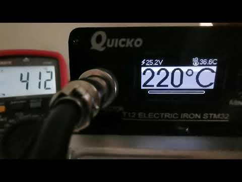
Video of operation here: (Project in active development, the features will change continuously)
- This project started by forking PTDreamer's firmware. Since then it became a separate project.
- Developed on STM32Cube IDE. Basic configuration is easily done in CubeMX (Included in STM32Cube IDE).
- Unified codebase, different hardware support based on profiles, very few files need to be changed.
- Supports all display modes: I2C, SPI, software and hardware+DMA (When connected to hardware pins).
- Uses U8g2 graphics library.
- Dynamic screen loading to save RAM resources.
- Extremely customizable, lots of options available.
- Code highly optimized to avoid wasting CPU power, slow devices still run great.
- Check Releases for downloads.
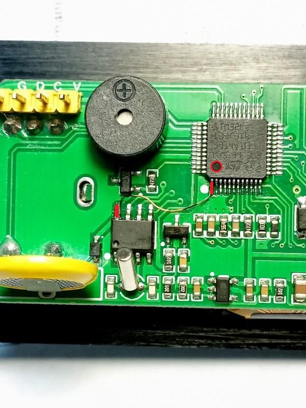
Check Boards readme for quick board identification.
Visit Dreamcat4 T12 controllers for more pictures and schematics.
BOARDS folder contains the build profiles.
KSGER Combo station is not supported!
The actual requirements are 10KB RAM and 64KB (*) flash.
(*) Currently the firmware has surpassed the 64KB limit, and uses the additional undocumented 64KB flash block.
(*) All 64KB devices have 128KB, with the second 64KB block untested from the factory, so not guaranteed to work.
(*) To date, I have found zero issues. Original KSGER firmware also does this.
(*) ST-Link checks the written data and the firmware uses CRC for settings, any error will be detected.
Clones / fakes:
Some controllers are using fake STM32 or compatibles, sometimes relabeled as genuine STM32, causing problems.
Check STM32 clone detection section to find out how to detect a genuine STM32.
- The only known working clone is CKS32.
- GD32, MM32 and CH32 have issues with the ADC converter.
- APM32 hasn't been tested yet.
Some issues caused by clones:
- Showing strange values in temperatures and voltage (ADC DMA issue), and/or getting NTC High/Low error even when NTC is disabled.
- Bootlooping / freezing / dying or going black after the initial setup screen (Uncompatible flash layout).
- Hardfault, Checksum Error bootloop.
Clones bring all kind of issues and there're too many of them, lots are relabeled and they even copy a genuine STM32 device ID, so in some cases it's almost impossible to figure out the actual device.
Some fakes worked well until recently, when the flash storage layout was updated.
The older v1.10.8 release is more compatible with fake devices, try it out in case you suspect having one.
No effort will be done to support fake / clones!
If your board came with a fake/clone, you can replace it with a STM32F103, they're pin-compatible:
- 48-pin: STM32F103C8T6, STM32F103CBT6.
- 64-pin: STM32F103R8T6, STM32F103RBT6, STM32F103RCT6, STM32F103RDT6, STM32F103RET6.
Currently supported controllers:
- Quicko T12-072: First gen Quicko, STM32F072 variant. Compatibility issues were fixed since v1.04.
- Quicko T12-103 First gen Quicko, same board but mounting a STM32F103.
- KSGER v1.5: Profile for STM32F103 (There are no other known CPUs used in this board).
- KSGER v2, JCD T12, T12-955, Handskit: Profile compatible with all STM32F101/2/3xx models.
- KSGER v3, T12-958: Profile compatible with all STM32F101/2/3xx models.
- T12-958 v2: Profile compatible with STM32F103. Needs a mod for battery to work.
Don't follow the version reported in the original firmware to identify your board.
To this day, the easiest way to quickly identify your controller version is by checking the OLED screen connection:
- 4 pin (I2C) = Generic v2 (KSGER/Quecoo/Handskit/etc.)
- 6 pin (SPI) = Generic v3
- 7 pin (SPI) = Only used by KSGER v1.5 or first gen Quicko, easy to differentiate.
For KSGER v2/v3: As long as use the correct firmware, any STM32 variant (101/102/103/C8/R8/CB/RB) will work.
There are several compatible/cloned boards in the market that will work fine with KSGER profiles.
T12-951, T12-952, T12-956, T12-959 use STC MCU, not supported by this firmware.
If you encounter any error or bug:
- Ensure your STM32 is genuine, check STM32 Clones.
- Throughly read the readme and manual and check if your issue is explained somewhere.
- If still no solution for it, open a new
issuespecifying:- Firmware version (v.XX) and type (KSGER V2, etc).
- If showing a screen with "Error: file xx.c, line n", mention this or attach a picture.
- If getting a Hardfault, attach a picture of the data shown on the screen.
If you want to check yourself, check thePCaddress shown in the screen and search it in the listing file (.list).
This will show where it happened in the program.
- You might also ask at Eevblog (English), 4PDA (Russian), Radiokot (Russian) forums.
First, make sure to read the Operating Instructions!
You can check the commit history to see what have been changed between builds.
The original firmwares are available [HERE]
Some KSGER firmwares require an activation code which can be generated with these keygens:
gen.htm stm32-ss-keygen-drz.py.
Be warned, usually the MCU will be read-protected, so you won't be able to read its contents, only erase it.
The simplest way to not loose the original firmware is actually to buy a new MCU, replace it, and store the original MCU in a safe place.
Any difference in the pinout will require firmware tuning, although one of the main proposits of this firmware is easing that.
There are some vulnerabilities that can be used to backup protected firmware:
- STM32 power glitching timing attack.
- PicoPwner. Tested, works very well.
Some commonly changed settings (Temperature setpoint, tip/profile selection) can be saved to the RTC SRAM, reducing flash wear.
The RTC needs a battery connected to STM32's VBAT pin, most boards have a battery connector for this.
- Install a 3.3V cell battery. Some boards have a resistor connected between VBAT pin and GND, will drain the battery, remove it.
- Enable
SYSTEM>Battery.
If the display has right/left line or is vertically shifted:
- Go to
System>Displaymenu. - Adjust
X/Y Offsetsuntil it's centered.

By default, never modify any PWM or Delay settings in the Iron menu. Doing so may cause such issues.
Also, new tips are often unstable, leading to temperature jumps.
Don't try to calibrate the tip in this state, neither set a high temperature, because it could go under control.
They usually settle after some burn-in time. It's recommended to set a medium temperature (250-300ºC) and leave it like that for 15-20 minutes until it stabilizes.
If the temperature is still unstable, try increasing the Iron > Delay value, allowing more time for the temperature signal to settle.
A damaged, loose or defective connection in the handle will also cause this issues. Ensure the contacts are clean.
There have been problems with some board/stations like:
- Noisy power supply
- Broken / badly soldered capacitors
- Bad Op-Amp
- Bad 3v3 regulator
If you're getting "NTC high/low" error even when disabling the NTC in settings, then your STM32 is fake.
Check Clones in Compatibility section and Clone fix option in System menu.
Buying a cheap high temperature meter is highly recommended!
These boards can have pretty different readings and tolerances. Even between T12 tips.
So the factory calibration is intentionally set lower than real, to avoid possible overheating problems.
Once you set the firmware, go to calibration and set there the real temperature measured with the external probe.
Ensure to read Calibration first!
To calibrate, go into Calibration > Start.
Attach the temperature probe before proceeding!
If the difference between measured and real is higher than 50ºC, the calibration will be aborted, telling you to go into Calibration > Settings and manually adjust the values.
The calibration settings menu has 3 calibration options: Zero set, Cal 250ºC and Cal 400ºC.
When you edit 250 or 400ºC value, the power will be enabled and the value applied in real time, so be careful!
The power will be removed when no settings are being edited.
Adjust each value until it's close to the target temperature. Repeat for each step and save.
Those values are only used by the calibration process, to prevent burning the tip if your board reads too low.
After adjusting, repeat calibration, this time it should work correctly.
The calibration results for the current tip can be seen in the tip settings menu.
Tip settings menu calibration values aren't meant to be another calibration menu, only for viewing (ex. reporting calibration results) and for backup/restore purposes.
In case you lose, wipe or reset the data, you can go back into that menu and adjust the values based on previous calibration results.
Zero calibration can't be manually restored, but it only takes few seconds to adjust.
Some amplifiers can introduce a small voltage offset that will translate into the cold tip reading 30-50°C higher than ambient temperature.
To fix that, follow this order exactly!
Tip power is removed in Calibration menu, inserting the tip before will heat it up and make cold calibration impossible.
Enter the Calibration menu, insert a completely cold tip now, enter Settings, adjust Zero set calibration and save.
After that, the offset will be compensated and the cold temperature will be normal.
It's highly recommended to recalibrate after changing this value.
Some KSGER controllers use a linear regulator to convert 24V to 3.3V, which is a very bad design and generates a lot of heat.
With the OLED displays, each pixel turned on consumes more power, and this firmware uses a larger font for displaying the temperature.
Thus, this firmware uses some more power. The design is so bad that the regulator will overload and shut down, resetting the board.
There're some options to fix this:
- Lower the display brightness to reduce the power consumption.
- Put a 100-150Ω 2W resistor in series with the regulator (24V->Resistor->LDO input). The resistor will drop part of the voltage and reduce the stress on the regulator.
- Replace the LDO with a better one or modify the board, adding a small heatsink to take away the heat.
- Use a small DC/DC step-down module to convert 24V to 5V, and feed 5V to the 3.3V LDO (best option, barely makes any heat).
After fully reading the documentation, if you still have problems or doubts, there're several forums with threads about this firmare:
For adding new languages, you have to modify these files:
Core/Inc/settings.h
- increment the value of
LANGUAGE_COUNTby one, - add your language identifier (
lang_xxxx) insystem_typesenum around row 100.
- increment the value of
Drivers/graphics/gui/screens/gui_strings.c
- copy the whole
[lang_english] = { … }section at the bottom ofstrings_tstrings, - replace
lang_englishwithlang_xxxxof the section you just copied and translate, - add your
lang_xxxxtoLangsat the bottom of the file.
- copy the whole
For adding new characters to the existing fonts symbols, there're some instructions here:
- I2C EEPROM - some boards have it, some doesn't. So internal flash storage is used for all. Also, the current settings don't fit in the commonly used 24C08 memory.
- Realtime clock - there's very little screen space. Use it for what matters, instead for showing a clock!
@Dreamcat4 has made a great research and documentation of T12 and STM32 related stuff: