The aim of this project is to develop an autonomous vehicle based on the Luas Light Rail System of Dublin, Ireland, using Arduino (Atmega-328p) & remote wireless supervisory control (using, XCTU & XBee or C#) with capability of ultrasonic obstacle detection & avoidance, self-parking, stopping at stations in its path & safely co-existing with other vehicles.

The Infra-Red module, Transmitter & Receiver circuits were designed & fabricated on a PCB from scratch to develop the vehicle.
A receiver circuit is developed which is used to identify different locations on the path i.e., the receiver circuit will be attached/mounted on to the vehicle and when it will pass through the stations, the IR signals emitted from the IR Emitter Diodes of the stations, will fall on the Receiver Circuit, which in turn will signal the vehicle to stop at the stations for some time.
The Receiver circuit is based on the PWM (Pulse Width Modulation) Technique. The MBD701 Schottky Diode acts as the Receiver which senses the Infra-Red Radiations and sends then to the circuit accordingly. The infra-red radiations received by the diode is sent to the op-amp comparator which are then further sent to the capacitor where the signal is rectified to proper DC pulse.

An infra-red sensor is placed at the Stations, so that when the vehicle will pass through it, the MBD701 Schottky diode will sense the IR Radiations and the vehicle will stop. Following this, after a certain interval the vehicle restarts its motion as the signals being sent to the diode from the comparator has been changed. Moreover, the first signal is sent directly from the diode to the comparator but the second signal is sent through the resister R2.
The Transmitter Circuit made for the stations will be placed at different locations on the path to be followed by the Buggy Robo Car. The transmitter will transmit signals for the receiver to receive, which would help us to know which station the vehicle has reached.
The DC-Jack converts the AC Voltage into DC Voltage after which the voltage regulator IC 78L05Z limits the max voltage to 5V which is the requirement of our experiment. The capacitors C1 and C2 are used as filters which remove some AC components remaining in the signal (if any) after converting into DC signal. The output of this circuit is used as input in our main circuit that is the circuit on the right side.
![]()
The RESET and VCC pins of the ATTINY45-20P microcontroller are connected to output of voltage regulator and all the other pins are used as I/O pins in the micro-controller excluding the ground pin. The Emitting diode SFH482 is placed on the stations, which will transmit IR signals to the micro-controller. Then the output from micro-controller is given to PCB headers which gives output as different frequencies which is detected by the receiver circuit on the vehicle so as to identify the different stations the vehicle has passed through. The LED used, shows that the transmitter circuit works properly.
The IR Sensor Module Circuit which will be placed on the Robo Vehicle, would help it to move on a predefined path as a line follower.
The IR emitter emits continuous IR Rays which on reflecting from the white surface of the path are received by the IR Receiver. An IR Output terminal of the receiver varies depending on the intensity of the IR Rays it receives. Since this variation cannot be analysed as such, this output is passed through a operational amplifier. When the IR Receiver does not receive a signal due to absorption by the black path line, the potential at the inverting terminal goes higher than the non-inverting input of the LM358MM IC. Thus its output goes low, and the LED does not glow. Therefore, when both left and right senses black, the vehicle stops as shown in the figure below.
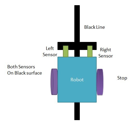
When the IR Receiver receives a signal reflected by the white light, the potential at the inverting end goes low. Thus the output of LM358MM IC goes high and the LED starts to glow indicating that the motor starts moving. When both left and right sensor senses white path then the Vehicle moves forward.

The Resistors R1, R2, and R3 ensures that minimum 10 mA current passes through the IR LED Devices like the photodiode and the LEDs.

