Control your electronics with an Google Assistant + Arduino UNO + ESP8266
- Android phone Marsmallow or higher or Apple phone (for Google Assistant)
- IFTTT Account
- Blynk App Account
- Arduino UNO
- ESP8266 (ESP-01) WiFi Module
- Some Jumper Cables
- Relay SRD-05VDC-SL-C (Optional)
- USB TTL Serial (Optional)
- 5V to 3.3V Logic Converter (Optional)
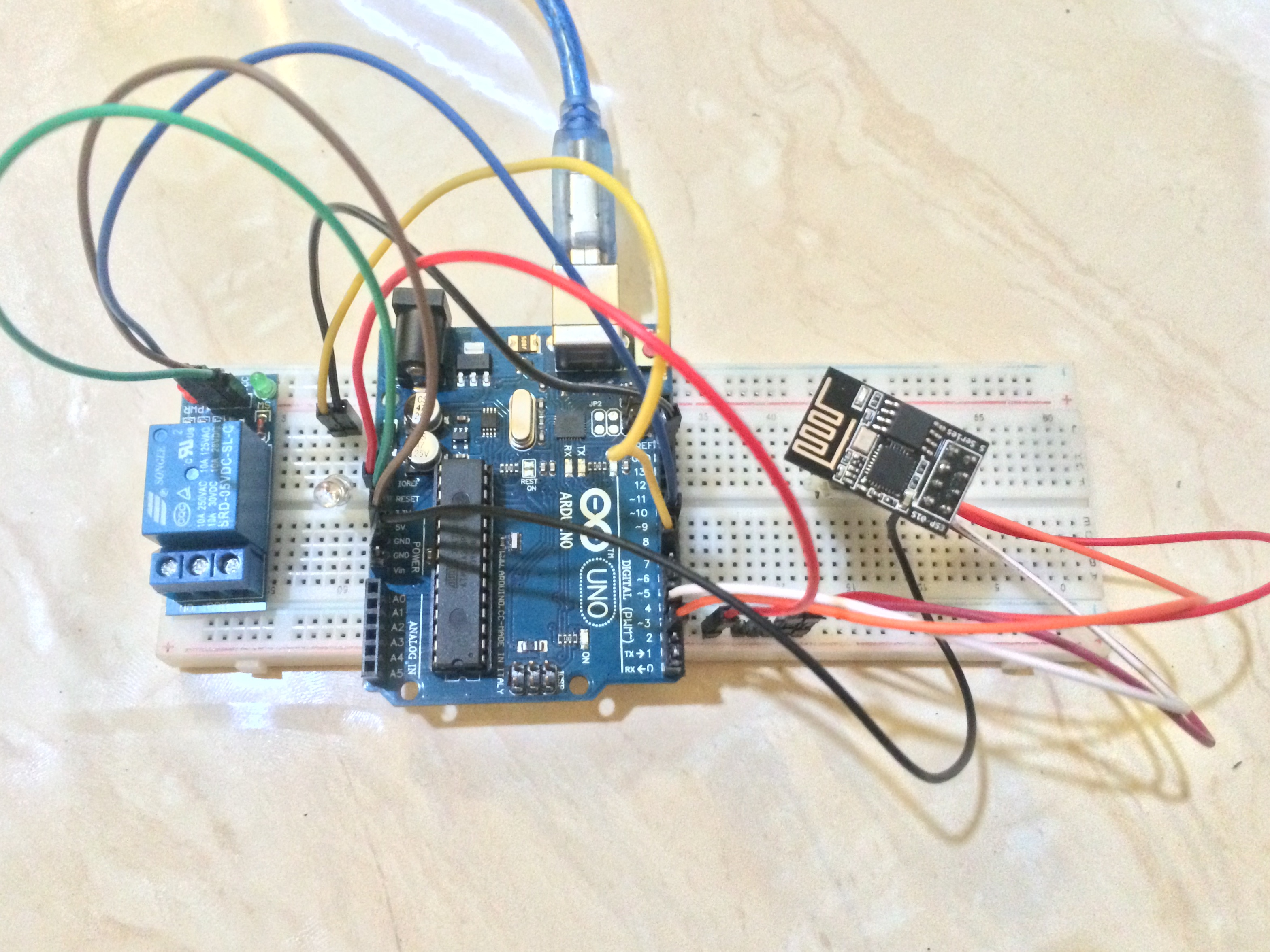
Use the PINOUT FINAL if you done with anything in this project.
The basic pinout of this project.
| UNO | ESP-01 |
|---|---|
| D2 (as TX) | RX |
| D3 (as RX) | TX |
| GND | GND |
| 3V3 | 3V3 |
| 3V3 | EN |
| UNO | LED |
|---|---|
| D7 | ANODE (+) |
| GND | CATHODE (-) |
| UNO | RELAY |
|---|---|
| D8 | IN |
| 5V | VCC |
| GND | GND |
Use this pinout only when you need to flash your ESP-01 Firmware
| ESP-01 | USB TTL |
|---|---|
| TX | RX |
| RX | TX |
| GND | GND |
| IO2 | GND |
| 3V3 | 3V3 |
| EN | 3V3 |
Use this pinout when you need to interact with AT Command only
| ESP-01 | USB TTL |
|---|---|
| TX | RX |
| RX | TX |
| GND | GND |
| 3V3 | 3V3 |
| EN | 3V3 |
Then use Serial Monitor from Arduino IDE to interact with AT
Use this if your ESP8266 have old or deprecated firmware installed. Remember to use PINOUT FLASHING ESP-01 for your jumper cable pinout in this step.
FIRMWARE ESP-01 :
Flash SDK First > Then Flash AT Afterward
esptool.py --port /dev/ttyUSB0 --baud 115200 write_flash --flash_size 1MB --flash_mode dio <MEMORY ADDRESS 0> <FILE-0.BIN> <MEMORY ADDRESS 1> <FILE-1.BIN> <MEMORY ADDRESS N> <FILE-N.BIN>
Memory Address :
| File | Address |
|---|---|
| boot_v1.2.bin | 0x00000 |
| user1.1024.new.2.bin | 0x01000 |
| esp_init_data_default.bin | 0xfc000 |
| blank.bin | 0x7e000 & 0xfe000 |
- Follow instruction on http://blynk.cc/getting-started/
- Download and install Blynk App for Android or IOS
- Install Blynk Library for Arduino IDE
- Open Blynk App
- Create 'New Project'
- Choose 'Arduino UNO' and 'WiFi' then click 'Create'
- Get the Blynk Auth Token. Note it
- Click on + sign on the top and one Button
- Click on Button and set the pin to 'Digital' and 'D7'. Set pin values to 1 and 0. Set switch to 'Push'
- Create same as step 5 for D8 pin
- Register IFTTT account
- Create Trigger (IF)
- Search Google Assistant
- Select 'Say a phrase with a text ingredient'. Enter everything you need.
- Choose Action (THEN)
- Search Webhooks
- Click on 'Make a web Request'
- Set the action
http://blynk-cloud.com/YourBlynkAuthToken/update/D7
Replace YourBlynkAuthToken with your Auth Token that you get from Setting Up Blynk step.
PUT
application/json
["1"]
and accept etc. That body part decides what you put in D7 pin. Apparenly this will make the led light up. Then you can define another IFTTT Applet to write ["0"] on the pin to turn it off. And create again for D8 pin.
Don't forget to import the Blynk Library to your Arduino IDE. You can follow this instructions for import the library to your Arduino IDE. Use OkGoogleArduino.ino sketch code. Don't forget to edit this variable:
char auth[] = "8f180320xxxxxxxxxc458c50faa";
char ssid[] = "iPhone 5S";
char pass[] = "11211111";
Replace it with your Blynk auth key, WiFi access point, and WiFi password. If your WiFi has no password, then use this.
char pass[] = ""
This is the log from Serial Monitor if everything is running without any problems.
22:19:06.581 ->     ___  __          __
22:19:06.581 ->    / _ )/ /_ _____  / /__
22:19:06.615 ->   / _  / / // / _ \/  '_/
22:19:06.648 ->  /____/_/\_, /_//_/_/\_\
22:19:06.682 ->         /___/ v0.6.1 on Arduino Uno
22:19:06.715 ->
22:19:07.148 -> [598] Connecting to iPhone 5S
22:19:10.381 -> [3815] AT version:1.6.2.0(Apr 13 2018 11:10:59)
22:19:10.414 -> SDK version:2.2.1(6ab97e9)
22:19:10.448 -> compile time:Jun  7 2018 19:34:26
22:19:10.613 -> Bin version(Wroom 02):1.6.2
22:19:10.613 -> OK
22:19:15.681 -> [9121] +CIFSR:STAIP,"192.168.200.30"
22:19:15.714 -> +CIFSR:STAMAC,"3c:71:bf:38:a9:de"
22:19:15.777 -> [9131] Connected to WiFi
22:19:26.315 -> [19739] Ready (ping: 44ms).
Sometime you'll get error like this from Serial Monitor.
ESP is not responding.
The default baud rate for ESP8266-01 is 115200. You maybe need to set it to 9600. Remember to use this PINOUT AT COMMAND MODE ESP-01 for your jumper cable pinout to enter AT Command mode.
AT
AT+UART_DEF=9600,8,1,0,0
If you still get ESP is not responding log, then maybe you need to recheck your jumper cable pinout. And because some reason you need to upgrade your ESP8266 firmware, so you can follow this FLASHING ESP8266 step.