This project explores the functioning, calibration and mathematics involved in getting comprehensible data from MPU6050 (a low-cost, highly accurate IMU with 6 DOF). IMUs can be very difficult to process and set up. MPU6050 uses I2C to communicate with the microcontroller it is connected to, and always acts as a slave device. Using the raw data from the accelerometer and gyroscope, I have tried to compute Roll and Pitch.
Note: I have built upon a few codes that I found on the internet, modified them with respect to my goals, and tried to combine their most striking features to give me the most accurate data. References are provided below.
The MPU-60X0 always operates as a slave device when communicating to the system processor, which thus acts as the master. SDA and SCL lines typically need pull-up resistors to VDD. The maximum bus speed is 400 kHz. The slave address of the MPU-60X0 is b110100X which is 7 bits long. The LSB bit of the 7 bit address is determined by the logic level on pin AD0. This allows two MPU-60X0s to be connected to the same I2C bus. When used in this configuration, the address of the one of the devices should be b1101000 (pin AD0 is logic low) and the address of the other should be b1101001 (pin AD0 is logic high).
---- Taken from Datasheet (Sec 9.2)
According to the above description: If pin AD0 is logic low, address of the device is b1101000 ( = 0x68). If pin AD0 is logic high, address of the device is b1101001 ( = 0x69). So in my case it is 0x68. (AD0 is connected to GND or left open)
Orientation data from gyroscope sensors is prone to drift significantly over time, so gyroscopic sensors are frequently combined with additional sensors, such as accelerometers or magnetometers to correct for this effect. (In this case, it is an accelerometer). The standard method of combining these two inputs is with a Kalman Filter, which is quite a complex methodology. Fortunately, there is a simpler approximation for combining these two data types, called a Complementary Filter. Also, gyroscope gives readings in degrees per second, so we'll have to measure the angular velocity (ω) around the X, Y and Z axes at measured intervals (Δt) and then multiply it with the interval.
Filtered Angle = α × (Gyroscope Angle) + (1 − α) × (Accelerometer Angle)
Gyroscope Angle = (Last Measured Filtered Angle) + ω×ΔtWhere,
α = τ/(τ + Δt)
Δt = sampling rate
τ = time constant greater than timescale of typical accelerometer noise
ω = Gyroscope reading in degrees/second (dps)
Check References
Take 1000 values and get the average value to calculate the offset or errors. This is then subtracted from the actual data to make it accurate.
Divide each value with it's sensitivity scale factor. This value is different for the gyroscope and accelerometer and depends on their configuration during the setup stage.
- Calculate Accelerometer Roll and Pitch
- Calculate elapsed time
- Use this formula to get gyroscope readings in degrees
Gyroscope Angle = (Last Measured Filtered Angle) + ω×Δt
- Use a complementary filter to combat drift
- Save the data for comparison during the next loop
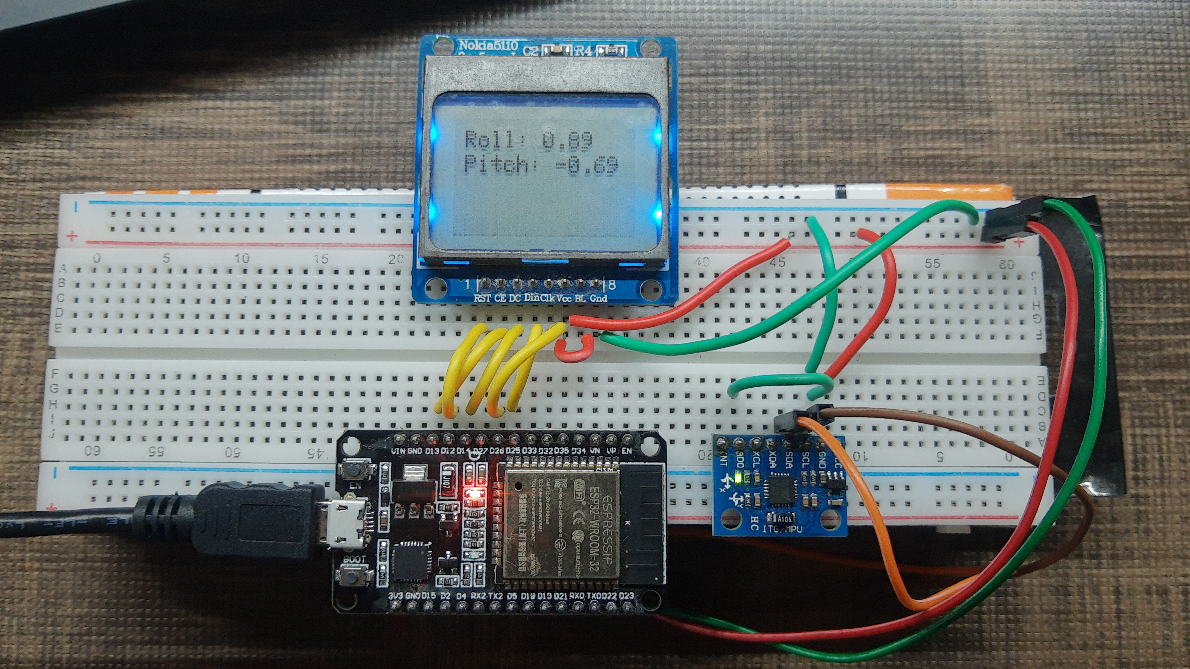
This is how it looks:
- Datasheet: https://www.invensense.com/wp-content/uploads/2015/02/MPU-6000-Datasheet1.pdf
- Register Map: https://www.invensense.com/wp-content/uploads/2015/02/MPU-6000-Register-Map1.pdf
- https://www.geekmomprojects.com/gyroscopes-and-accelerometers-on-a-chip/
- https://dronebotworkshop.com/mpu-6050-level/
- https://howtomechatronics.com/tutorials/arduino/arduino-and-mpu6050-accelerometer-and-gyroscope-tutorial/
- https://www.electronicwings.com/sensors-modules/mpu6050-gyroscope-accelerometer-temperature-sensor-module
- https://playground.arduino.cc/Main/MPU-6050/#info
- Formulae
- https://stackoverflow.com/questions/55866808/attitude-estimation-from-accelerometer-and-gyroscope-of-an-imu
- https://stackoverflow.com/questions/3755059/3d-accelerometer-calculate-the-orientation
- Configuration
- https://medium.com/@kavindugimhanzoysa/lets-work-with-mpu6050-gy-521-part1-6db0d47a35e6
- tockn/MPU6050_tockn#4
- I2C Write: https://forum.arduino.cc/t/how-to-read-a-register-value-using-the-wire-library/206123/2
- My Notes on MPU6050 Register Setup
