2. Connecting CNC xPRO
- Hookup Guide
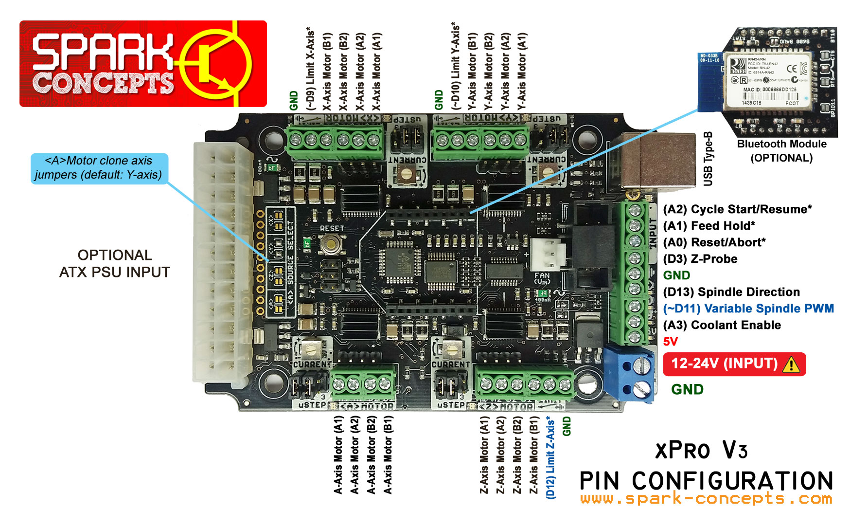
- xPro V3 Pinout
- Connect stepper motors
- Connector Pinouts
- Setting Motor Current
- 4th Axis
- Configure Limit Switches
- Connect Physical Controls (start/resume, hold and reset/abort)
- Output Accessory Functions
- Power Switch (e-stop)
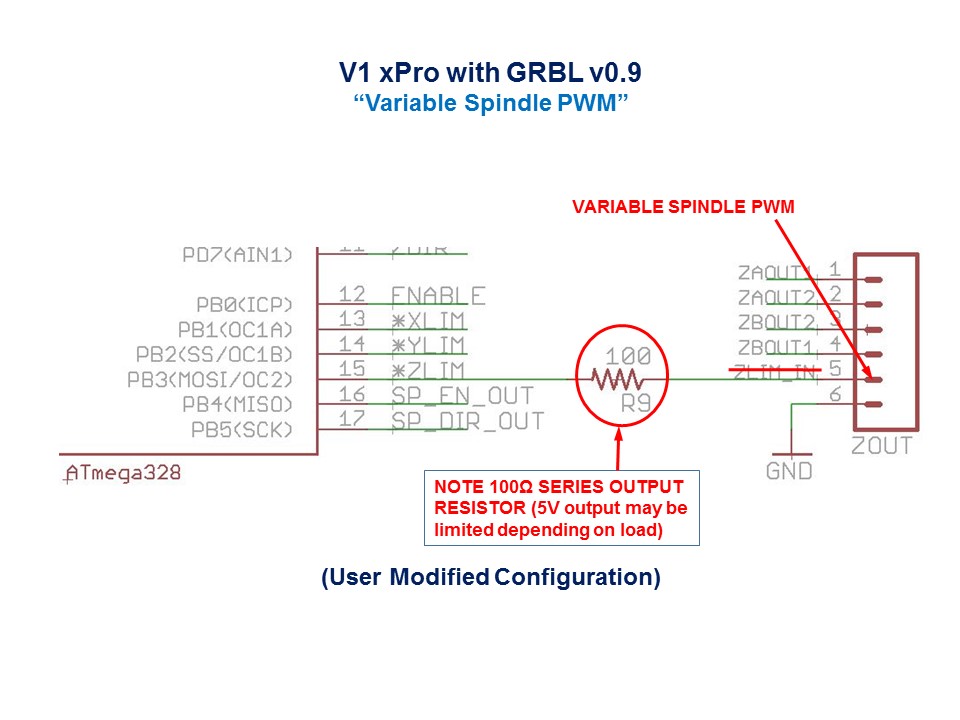
- xPro V1 Users Upgrading to Grbl v0.9
- Grbl v1.1 CNC xPro V3 Pinout
- Grbl v0.9 CNC xPro Pinout
- Grbl v0.8 CNC xPro Pinout
- xPro V1 Schematic
- xPro V2 Schematic
- xPro V3 Schematic
- *Download Universal G-Code Sender
- *Configuring GRBL
*external links
.jpg?raw=true%0A)
V1 and V2 ONLY when using a non-ATX PSU, Over-Volt and Over-Current protection is recommended. For ALL xPro versions: before connecting your xPro for the first time, use a multi-meter to measure power supply voltage and adjust to at or below 24VDC (if you can), some go quite a bit higher than the 24V they're labeled

It is recommend that a 15A fast blow or 10A slow blow fuse is used. A TVS zener diode is also recommended for V1 and V2 ONLY - V3 includes a built in TVS diode (see wiring diagram below for V1/V2 recommendation - note: TVS Diode polarity [Cathode to "+VDC", Anode to "GND"). Unlike ATX power supplies, most non-ATX PSU's are not filtered to produce clean/stable power under varying load. With non-ATX PSU's, the addition of a TVS diode will aid in suppressing and preventing potential damage due to PSU instability when initially powered ON and/or due to transient back-emf produced as steppers ramp up/decelerate.

*Here are some suggested part numbers and links to set this up:
- (TVS DIODE) part number: SA24A
- (FUSE HOLDER) part number: 01530002H
- (FUSE) part number: 0297015.WXNV

 *damaged due to over-voltage (faulty PSU)

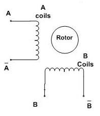
- How to: verify coil wires
- Simple verification of 4 wire stepper motors:
- Using a multi-meter, resistance Set the Ohmmeter to the lowest resistance scale.
- Attach one of the wires to the meter and, in turn, check each of the remaining three
- Mark the wire that gave a reading and mark the first wire you started with (coil A)
- The remaining two wires will be coil B
NOTE: switching the polarity of either (one) coil will reverse the stepper's direction
- Connect stepper motor wires to 3.5mm motor terminals or 4-pin 0.1" (2.54mm) male headers

Each of the motors has a 4 terminal screw-down block wired as:
Pin | Motor Phase (Output) | Description
----|--------------------- |-------------
1 | A1 | Coil A Positive
2 | A2 | Coil A Negative
3 | B2 | Coil B Negative
4 | B1 | Coil B Positive
Attach one pair to A1/A2 and the other pair to B1/B2. If the motor spin needs to be inverted you can do this in hardware by reversing one of the pairs (e.g. swap A1 with A2 and vice versa), or in software by using the polarity setting.
Connect the motors to the xPro, remembering: NEVER CONNECT OR DISCONNECT BOARDS OR MOTORS WHEN ANYTHING IS POWERED.

WARNING: Do not force or turn the current trim pots past the detents.
-
Motor current for each axis is adjusted with the "current" trimpot nearest that axis. Clockwise increases current, counter-clockwise decreases current.
-
You want the motor current set slightly above the range you need for your application, but not much higher. Overdriving the motors draws more current and risks overheating or thermal shutdown.
A motor that is receiving too much current may cause it to run "rough". If you experience this try backing off the current and see if the motor runs more smoothly.
Overstressing or overcurrent will cause your motors to heat up substantially. Stepper motors draw the most current when they are not moving so this is when they will get the hottest. Motors that run too hot run the risk of being ruined by demagnetizing.
** Follow these steps to set the motor current:
- Set current to zero by gently turning the trimpot all the way counter-clockwise
- Send a relatively slow move to that axis, something like g1 f400 x50
- Adjust the current up (clockwise) until the motor moves or starts humming (meaning it's stalled)
- Try the move again at this new setting. If it's still stalled increase the current some more and try again.
- Once the motor is running turn the current down until it stops. Mark this as the low current spot.
- Run the motor again and adjust current up until it runs rough or goes into thermal shutdown (see below*).
- Now back off until the cycling stops and the motor runs smoothly, and mark this as your upper limit.
- When you actually run jobs you want to back off the current as much as you can while still running reliably to somewhere between your upper and lower limit. This will minimize board and motor heating.
*If the motor starts to cycle on and off; this indicates thermal shutdown is occurring. Cycling will occur under thermal shutdown, and only gets more severe as the current goes up - where it appears the motor is stuttering.
####The xPro is 4-axis ready (3-axis control with GRBL version 0.9J - 4th axis, "< A > MOTOR" may be cloned; XYZ + clone axis)

Currently GRBL firmware version 0.9j only supports 3 axis – hopefully a 4 axis firmware version will be coming soon! (Updating GRBL Firmware)
The ‘A’ driver is best used as a clone of the ‘X’ ‘Y’ or ‘Z’ (default: ‘Y’ axis clone). In order to change which axis commands the ‘A’ axis, you must bridge the solder jumpers to that /and only that corresponding axis, see above image (default ‘Y’ axis)
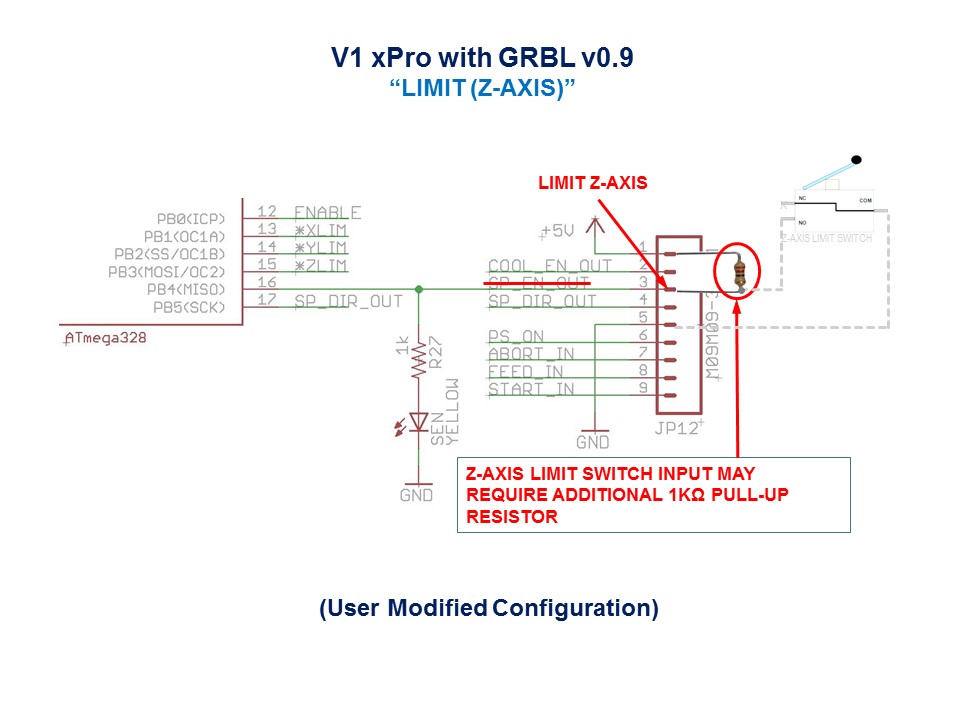
Once you decide that you're ready or would like to enable homing and/or hard limits, you'll need to enable Grbl "Hard Limits" (Grbl v0.8)/(Grbl v0.9) and connect a normally-open limit switch to each of the limit pins (Limit X-Axis, Limit Y-Axis and Limit Z-Axis).

These Limit(X,Y & Z) terminals are already held high with an internal pull-up resistor, so all you have to do is wire the NO (Normally Open) side of the switch terminal to ground. So when you close a switch, the switch will pull the limit pin to ground. If you'd like to have hard limit switches on both ends of travel of an axis, just wire two (or more) limit switches in parallel to the axis limit pin and ground.

In Grbl v0.8/v0.9, there are outputs for cycle start, feed hold, and reset runtime commands, so you can have physical control buttons are your machine. Just like the limit pins, these pins are held high with an internal pull-up resistor, so all you have to do is connect a NO (Normally-Open) momentary switch to each pin and to ground. Again make sure you practice good wiring methods to minimize external electric noise on the input pins. Note that just about any switch will work for these - signals are ~micro-Amps.
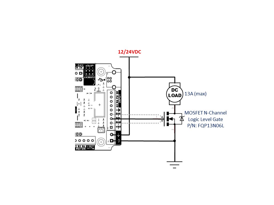
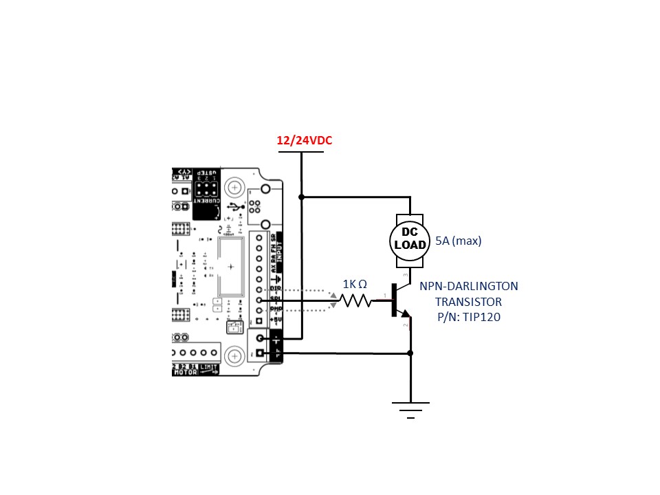
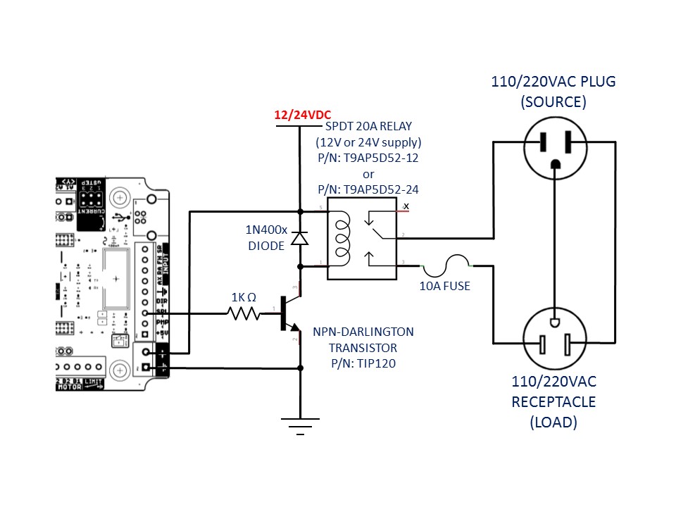
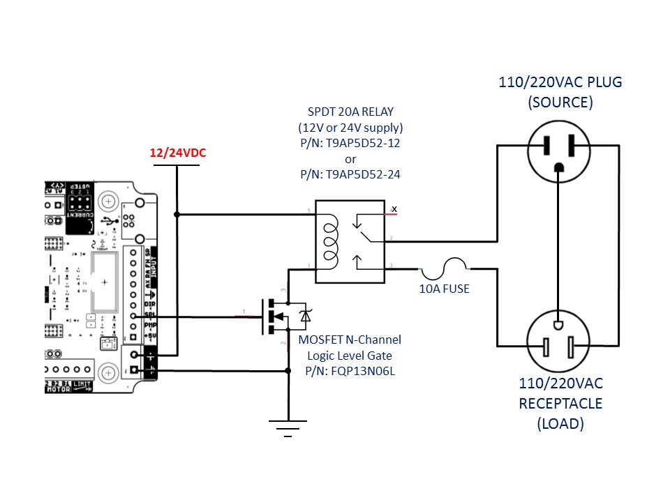
If you have a desire or need for spindle or coolant control, Grbl will toggle these output pins (D12/D11*, D13, A3) high or low, depending on the g-code commands you send to Grbl. *With v0.9 and variable spindle PWM enabled, the D11 pin will output a range of voltages from 0V to 5V depending the spindle speed g-code command. 0V indicates spindle off in this case. Since these pins are all application dependent in how they are used, we'll leave it to you on how to control and use these for your machine. Check out below for some recommended applications. You can also hack the spindle and coolant control source files to easily alter how they work and then compile and upload your modified Grbl through the Arduino IDE.

 General Solder Bridge Removal - CLICK HERE
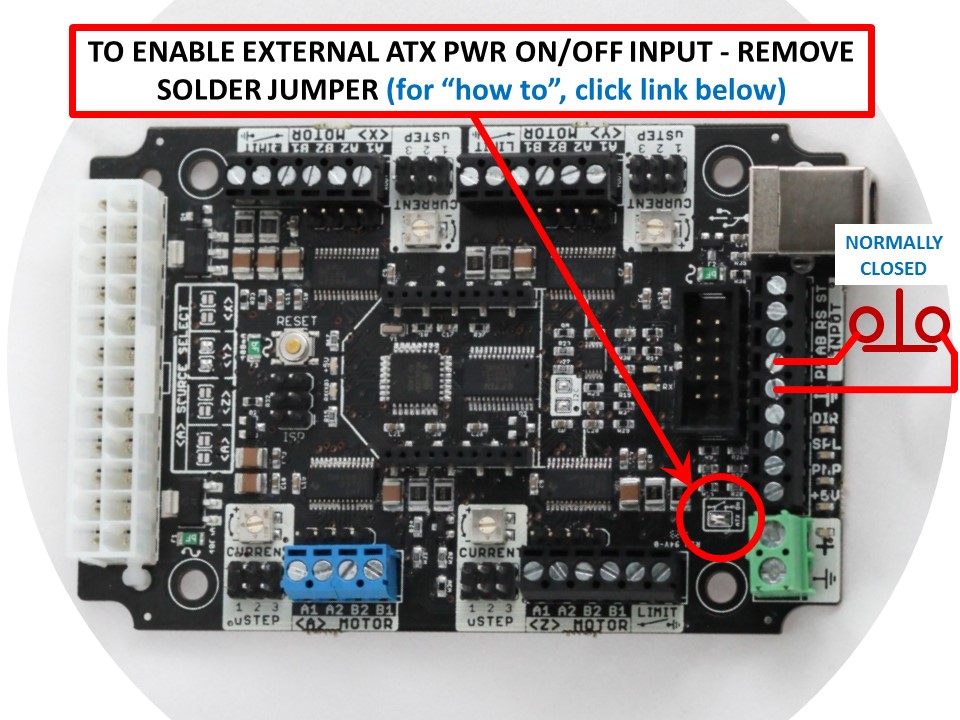
- Before you proceed, first remove the ATX-ON solder jumper if you plan to connect an external switch (see above)
Similar to the limit/control function inputs, the ATX power ON/OFF pin is held high, so all you have to do is connect a NC (Normally-Closed) mushroom style switch between this terminal and to ground (when the switch is connected to ground, this ground logic signal will tell the power supply will turn-on). By default the xPro is configured such that this signal line is always pulled to ground - so ensure you've removed the "ATX-ON" solder jumper (above). Note: since this method uses the ATX power-on logic signal wire - the switch current rating is insignificant (~micro-Amps).
Typical "e-stop" Operation:
- Normal Operation (Powered ON): e-switch is pulled out
- Emergency Stop (Powered OFF): e-switch is depressed
The brute force method:
- Place a SPST(or similar) in series with the 12-24VDC supply
- Ensure that you're switch is rated to at least a 10AMPS(min) @ 25VDC(min)


- Download the Quick Hook-Up Guide
NOTE: limit Z-axis and spindle enable pin assignments have changed
Click here for hardware pinout.
-
Spindle Enable is now Limit Z-Axis*
-
Limit Z-Axis is now Variable Spindle PWM*