Geometry context
The geometry context is for everything related to geometry definitions. The geometry can either be read from file, or generated. By default all application can generate a unit line/square/cube. The geometry generated can be controlled through a number of attributes.
Attributes:
- rational - True to use a rational basis.
- X0 - Lower left corner of geometry X0.
- L - Length of line. Only used in 1D.
- scale - Scale for geometry
- Lx, Ly, Lz - Length in the respective directions.
-
sets - True to generate default topology sets, these are then used in boundaryconditions:
- Boundary (All 6 boundary Faces (volume models) or 4 boundary edges (surface models))
- Corners (All 8 (volume models) or 4 (surface models) corner vertices)
- EdgeX (X=1..12, one of the 1D-edges. 4 edges for surface models, 12 edges for volume models)
- FaceX (X=1..6, one of the 6 boundary faces (volume models only))
- VertexX (X=1..8, one of the corner vertices)
Example:
<geometry>
  <partitioning procs="2">
    <part proc="0" lower="1" upper="3"/>
    <part proc="1" lower="4" upper="5"/>
  </partitioning>
  <patchfile>foo.g2</patchfile>
  <refine lowerpatch="1" upperpatch="3" u="1" v="2" w="3"/>
  <raiseorder lowerpatch="1" upperpatch="3" u="1" v="2" w="3"/>
</geometry>Use this to load a geometry from a .g2 file.
- Attributes: None
- Value: The g2 file
Example:
<patchfile>foo.g2</patchfile>Use this to load node numbering from a .gno file. Note: this is deprecated.
- Attributes: None
- Value: The gno file
Example:
<nodefile>foo.gno</nodefile>Use this to partition your geometry for parallel computations. This partitions the available patches across a set of processors. You can specify this partitioning in two ways. You can have several partitionings defined in your input file, the appropriate one will be chosen based on the available number of processes on runtime.
- Attributes: procs, nperproc
- Value: <part> tags or None
Simple example:
<partitioning procs="4" nperproc="1"/>More involved example:
<partitioning procs="2">
  <part proc="0" lower="1" upper="3"/>
  <part proc="1" lower="4" upper="5"/>
</partitioning>A <part> tag specifies a part of a partitioning.
- proc - Process this part is for.
- lower - First patch on this process.
- upper - Last patch on this process.
Example:
<part proc="x" lower="y" upper="z"/>Use this to refine your geometry definition (knot insertion, or h-refinement).
Attributes:
- patch - Use this to refine a particular patch.
- lowerpatch - The lower patch number.
- upperpatch - The upper patch number.
- u, v, w - The number of knot-insertions to do for each existing knot-span in the given direction (uniform refinement).
- dir - The direction to refine in. Used with nonuniform refinements (one indexed).
Value: If empty, uniform refinement is assumed. Otherwise it contains either the explicit relative knot positions (in range [0.0,1.0]), or specification of a graded or biased refinement (see examples below).
Example:
  <refine lowerpatch="1" upperpatch="3" u="1" v="2" w="3"/>
  <refine patch="4" dir="1">0.01 0.05 0.10 0.5 0.7</refine>
  <refine patch="4" dir="2">graded 5 1.2 0.0 0.6</refine>
  <refine patch="5" dir="1">biased 5 3.0 0.1 0.6</refine>
In the third example containing the keyword "graded" (or just "g"), the first numerical value is the number of knot-insertions (for each existing knot-span) and the second value ((\alpha)) is the relative size of two neighboring knot-spans, i.e. (du_{i+1} = \alpha du_i, i=1 \ldots n-1). The two last values are optional start and stop parameters (relative, in range [0.0,1.0]) for the graded refinement. Their default values are 0.0 and 1.0, respectively which implies the entire knot-span.
In the fourth example containing the keyword "biased" (or just "b"), "), the first numerical value is the number of knot-insertions (for each existing knot-span) and the second value (\alpha) is the bias ratio, i.e., the ratio of the last knot-span to the first knot-span; (du_n = \alpha du_1). The two last values are optional start and stop parameters (relative, in range [0.0,1.0]) for the biased refinement. Their default values are 0.0 and 1.0, respectively which implies the entire knot-span.
Use this to raise the order of your geometry definition (order elevation, or p-refinement).
Attributes:
- patch - Use this to order elevate a particular patch.
- lowerpatch - The lower patch number.
- upperpatch - The upper patch number.
- u, v, w - The number of orders to raise for the given direction.
Value: None
Example:
<raiseorder lowerpatch="1" upperpatch="3" u="1" v="2" w="3"/>Use this to group topological entities. Used for applying boundary conditions, etc.
- Attributes: None
- Value: One or more <set> tags.
Attributes:
- name - The name of the topology set.
- type - The type of the topological entities in this group (face, edge, vertex).
- closure - Whether or not to include end points (closed, open).
Value: One or more <item> tags
#### item Attributes:
- patch - The patch this entity exists on
Value: Space separated list of entities (one indexed).
Example:
<topologysets>
  <set name="Homogenous" type="edge">
    <item patch="1">4</item>
  </set>
  <set name="Neumann" type="face">
    <item patch="1">1 2 3</item>
  </set>
  <set name="fixpoint" type="vertex">
    <item patch="1">1 2 3</item>
  </set>
</topologysets>
The convention for the topology entities in 2D: 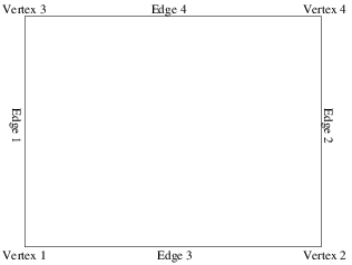
The convention for the topology entities in 3D:
Vertices:

Edges:

Faces:

Use this to define the topology of your patch blocks. A topology block consists of one or more <connection> tags.
- Attributes: None
- Values: <connection> tags
A connection tag has several attributes:
-
master - Patch ID for master in connection.
-
midx - Index on master patch.
-
slave - Patch id for slave in connection.
-
sidx - Index on slave patch.
-
reverse - True to connected edges in reversed order (only used in 2D).
-
periodic - True to connect edges in a periodic fashion (ie non-matching coordinates are ok).
-
basis - The bases to apply the boundary conditions to. Is a one indexed, string with 1, 2, 12, .. or 0 for all bases.
-
dim - Dimensionality of connection. 0 for a vertex, 1 for a line, 2 for a face.
-
orient - Orientation of connection. 0 or 1 in 2D, 0..7 in 3D.
-
Attributes: master, midx, slave, sidx, reverse, periodic, basis, dim, orient
-
Values: None
Example:
<topology>
  <connection master="1" midx="4" slave="2" sidx="3"/>
</topology>The existence of this tag enables the use of linear, triangular elements in 2D.