This repository contains all information regarding the code of STM32F401RE for the Pothole Detector project.
This board is part of a bigger system, it will be connected to other board via I2C and it will send data through LoRa. The code sends via I2C the events detected from LSM6DSL (x-nucleo-iks01a2) accelerometer.
Complete project can be visited here
This project was done using a generated code by System Workbench toolchain distributed by STMicroelectronics, you can download the pack here as well as eclipse IDE.
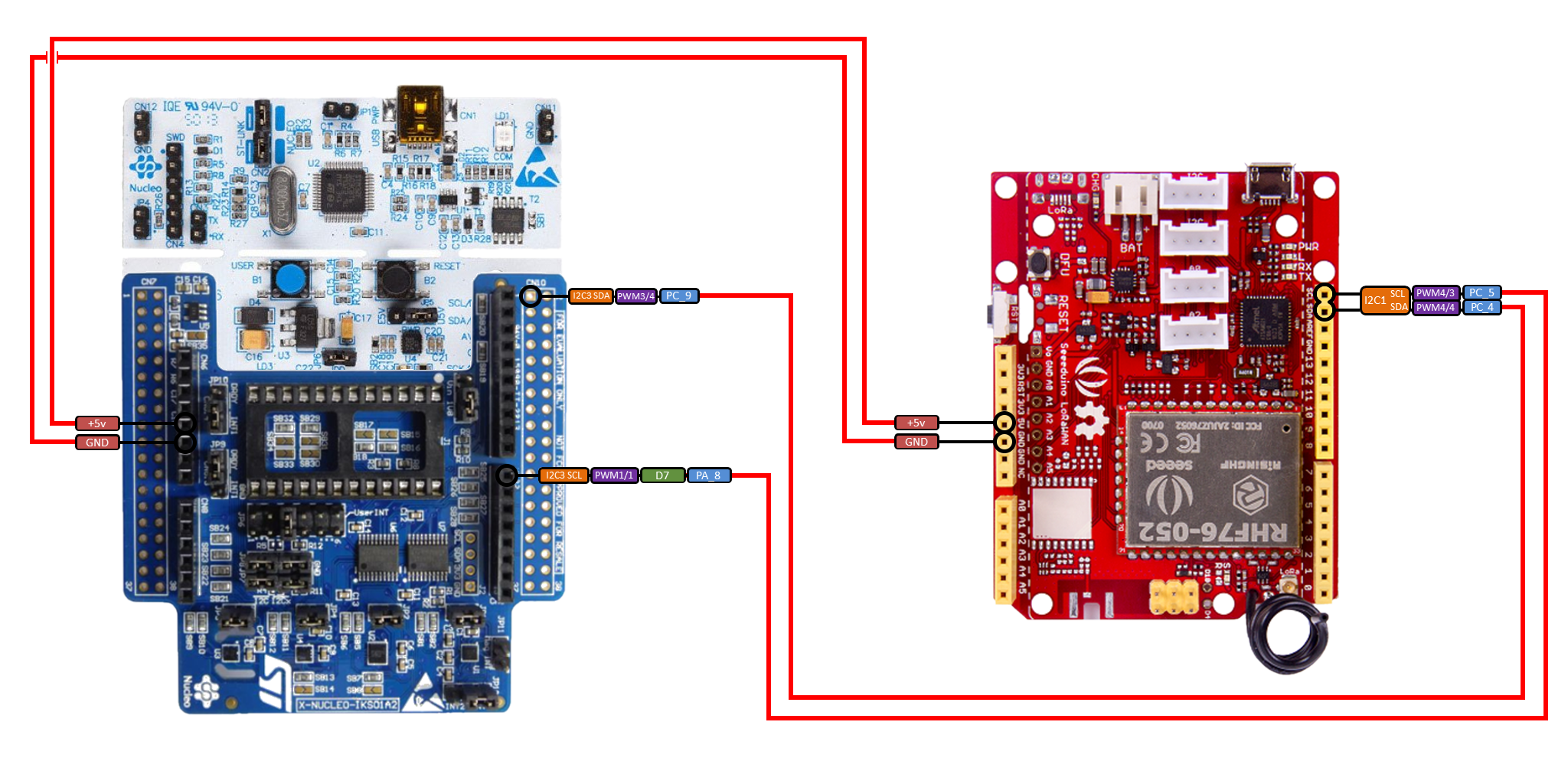
| STM32F401RE (X-NUCLEO-IKS01A2) | Seeeduino LoRaWAN w/ GPS |
|---|---|
| PA8 (I2C3 SCL) | PC5 (SCL) |
| PC9 (I2C3 SDA) | PC4 (SDA) |
| +5V | +5V |
| GND | GND |
- The code contains all libraries used by peripherical modules but make sure you all have a working environment.
- Import the code by manualling clicking right on the Project Explorer
- Build the code and run it.
- If it fails then make sure libraries of X-NUCLEO-IKS01A2 (Drivers/BSP) dependencies are added inside project properties.
You can see basic information of what's happening inside the board.
- LED: Show status of internal functions
| Loops | Functionality |
|---|---|
| Inf | Internal error, needs manual reset |
| 3 | Timed mode is selected |
| 6 | Burst mode is selected |
- Button: via SERCOM (using Putty, for example) you can view:
| Times button pressed within 1 s | Functionality |
|---|---|
| 1 | Print counted events and timer status |
| 2 | Switch between Burst/Timed mode |
| 3 | Test I2C connection and send events |
- Timed mode means every detected events is stored until a timer interrupts. If Timer interrupts it's sent via I2C to Seeeduino.
- In Burst mode there is no need to wait for the Timer IT so every detected events will be sent instantly to Seeeduino via I2C.
You can view all basic information like detected potholes and low-level processes by uncommenting the DEBUG_MODE define in main.c file and openning a SERIAL/USART terminal monitor.
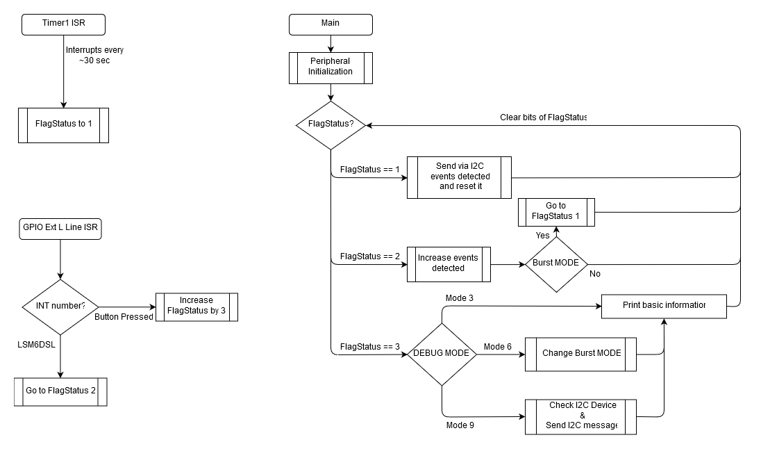
STM32F401RE is configured to have several interrupts.
- Timer ISR. It's used by Timed mode so everytime it interrupts, the stored events detected is sent via I2C if it's non-zero.
- GPIO Ext L line ISR. It's used twice by Button (GPIO C - GPIO_PIN_13) and LSM6DSL INT2 (GPIO B - GPIO_PIN_4)
- USART and I2C. It's managed internally by native libraries.
Libraries used:
- STM32F4xx_HAL_Driver. For GPIO, I2C, Timer and UART management.
- BSP. For X_NUCLEO_IKS01A2 accelerometer (x_nucleo_iks01a2_accelero).
- Peripherals is configured to do:
- Timer0 interrupt every 30 second via MX_TIM1_Init function. When it's triggered go to StatusFlag 1.
- USART2, I2C3 is configured via MX_USART2_UART_Init and MX_I2C3_Init.
- GPIO External interrupt for GPIOC Pin 13 (built in button) and GPIOB Pin 4 (LSM6DSL INT2). Both done with BSP libraries.
- I2C2. For X-NUCLEO-IKS01A2 communications, it's initialized by BSP_ACCELERO_Init.
- Accelerometer is configured using initializeAllSensors and enableAllSensors, internally it uses BSP_ACCELERO_XXX functions.
- Now X-NUCLEO-IKS01A2 has its LSM6DSL running, when more than X g's (G-forces more than a threshold) then it will call to STM32F401 via HAL_GPIO_EXTI_Callback, notifying a new data is received via I2C2.
- In HAL_GPIO_EXTI_Callback, MCU go to StatusFlag 2 if the Pin number interrupt is LSM6DSL INT2 (GPIO B - GPIO_PIN_4), otherwise StatusFlag is StatusFlag plus 3 (See step 7)
- In StatusFlag 2, the data received via I2C2 is decoded and interpreted using BSP_ACCELERO_Get_Event_Status_Ext getting a status flag. If status.FreeFallStatus is true, the stored events (mems_events_detected) is increased. In burst mode go directly to StatusFlag 1.
- In StatusFlag 1, if stored events (mems_events_detected) is non-zero then value is sent via I2C3 using HAL_I2C_Master_Transmit function.
- In StatusFlag 3, mode between Timed or Burst can be selected pushing twice within 1 second the built-in button. Once in status 3 it waits 500 ms so if HAL_GPIO_EXTI_Callback is called again, StatusFlag is increased. When switch case structure reads StatusFlag then it could be 3/6/9, see step 3 for number interpretation.