This codebase is designed to synchronize an RGB LED illumination system with the rolling shutter of a NanEye2D monochrome camera and display real-time color video dependent on a calibration step and linear unmixing algorithm. This allows color video to be produced from an image sensor with no Bayer mask, increasing the effective spatial resolution. For extremely small cameras such as those used in medical imaging and endoscopy with an imaging area of only 250x250 pixels this increased resolution can make a large difference in the usability of the images.
More information about the equipment, example image/video outputs, and quantitative results of this system can be found in:
Please feel free to reach out to Jordan Anspach at jordananspach@gmail.com with any questions. More details and documentation is available by request.
A video of the system being demonstrated can be found at: https://doi.org/10.6084/m9.figshare.22639246.v1
- The main GUI file is the
NaneyeinterfaceUSB2.mfile in the MATLAB folder. Run this to start the program. This code is an edited version of the MATLAB API available from ams for use with their cameras and interface modules. This API can be found on their website: https://ams.com/en/naneye#tab/tools - Place a completely white target such that it covers the entire imaging area and click the "Calibrate" button.
- Adjust camera register values as desired.
- Let the calibration process run for at least a couple seconds to ensure adequate images are saved and then click the "End Calibration" button.
- Review the pop-up window showing the captured images and repeat steps 2-3 until they match the expected pattern.
- Click the "Prepare to Start" button and wait for the LEDs to start rapidly blinking.
- Click the "Confirm Start" button to begin the real-time video computation and display.
- Adjust parameters such as the Red, Green, and Blue channel weights as desired.
- Click the "Record" to begin saving the processed video.
- Click the "Stop" button to end the program and the recording if it had been started. The last three raw frames from the camera will be displayed for the user to inspect.

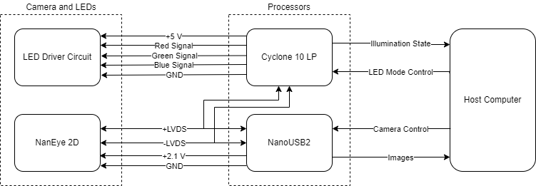
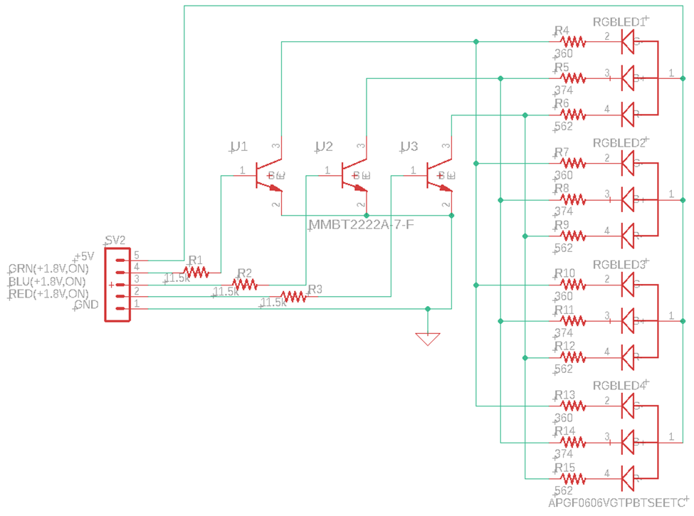
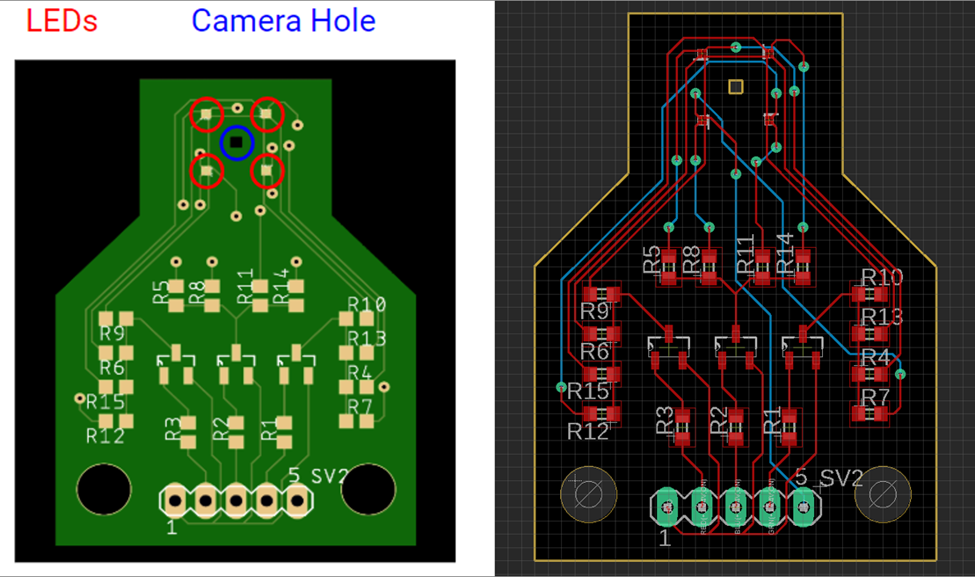
Custom PCBA with four Kingbright APGF0606VGTPBTSEETC LEDs controlled by the Cyclone 10LP I/O driving MMBT2222A-7-F BJTs as switches.
Miniature image sensor with integrated optics. More information: https://ams.com/en/naneye
Communicates with a NanEye2D camera over a USB connection to a PC. Capable of writing values to the camera's registers and reading image data. More information: https://ams.com/nanousb2-eval-kit
FPGA development board takes in LVDS signal from camera to monitor for end-of-frame, controls LED timing, and shares LED state information with the Host PC MATLAB application over USB.
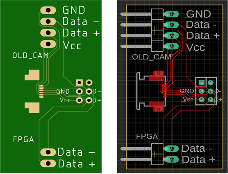
This simple PCBA splits the LVDS bus from the camera and allows both the FPGA and USB interface to easily connect to and monitor for data. This board consists solely of connectors. In future iterations dedicated LVDS splitting circuitry should be implemented to maintain signal integrity.
Quartus Prime was used for all VHDL programming.
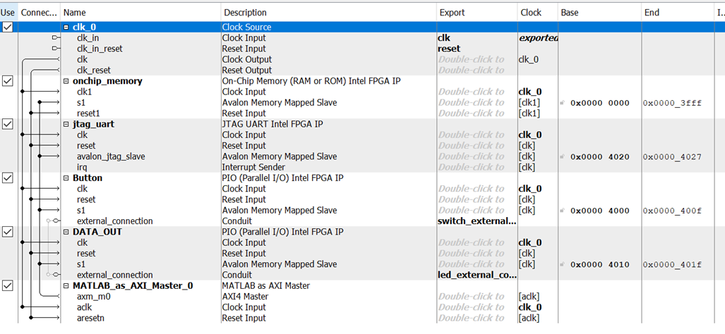
The Cyclone 10LP monitors the camera's LVDS bus and feeds the incoming values into a FIFO register. The FPGA is looking for the end-of-frame signal from the camera which indicates that the LED state should be changed and updated to the Host PC. The end-of-frame signal from the camera is 48 bits of consecutive zeroes. Once this end-of-frame is detected, the LEDs are turned on/off as dictated in our R-G-B sequence and the updated LED state is sent to the Host PC over USB. The illumination states are different during the calibration step since only one color is being switched on/off at a time. This requires that the Host PC also send data to the FPGA indicating what stage of the process the user has selected. To communicate with the Host PC over USB, the "MATLAB as AXI Master" process was used to allow MATLAB on the Host PC to access on-board memory locations using simple functions. See the QSYS file contents and connections below.
MATLAB 2019b was used for all Host PC progamming. The Host PC acts as the "hub" of the system, provides the user interface including control and video display, as well as all of the image reconstruction processing. This code is well commented and the theory of operation is explained in the paper cited above. For more details please contact Jordan Anspach at jordananspach@gmail.com.