This fork of the repo has been modified to provide HV programming capability to various MCU's as described below. This capability can be disabled if using or Making a UPDI programmer. For both types of programmers, all unused pins will have their pullups enabled.
These HV UPDI programming designs are open source and made to work with tinyAVR® 0-series and 1-series MCUs, megaTinyCore and the Arduino IDE. This allows using the additional configuration settings for the UPDI pin without the fear of getting locked out from the MCU. Normal workflow when using the Arduino IDE is preserved.


Firmware (jtag2updi) support for HV programming is controlled by the USE_HV_PROGRAMMING option in sys.h - uncomment #define USE_HV_PROGRAMMING to enable these features. Be sure that your hardware is consistent with the specifications described herein; when this is used with a non-HV capable programmer, it will generally not function as designed. The mechanism by which these failures occur involves two floating analog pins, and the exact behavior is influenced by the voltages they settle on, so ostensibly identical programmers can produce very different output.
Defaults: SpenceKonde jtag2updi: HV UPDI tool is disabled, Dlloydev jtag2updi: HV UPDI tool is enabled.
| HV UPDI Programmer | 1. Arduino Nano | 2. DIY AVR132DA | 3. DIY ATmega4809 | 4. DIY ATtiny | 5. DIY Nano |
|---|---|---|---|---|---|
| Feature | 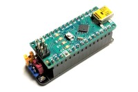 |
 |
 |
 |
 |
| Target Voltage | 5V | 3V-5V | 5V | 5V | 5V |
| Programmer's MCU | ATmega328P (16MHz) | AVR132DA28, AVR132DA32, AVR132DA48, AVR132DA64 (24MHz) | ATmega4809, ATmega4808, ATmega3209, ATmega3208, ATmega1609, ATmega1608, ATmega809 or ATmega808 (16MHz) | ATtiny1604, 1614, 1606, 1616, 3216, 1607, 1617 or 3217 (16MHz) | ATmega328P (16MHz) |
| MCU Board Required | Yes (Arduino Nano) | No | No | No | Yes (Arduino Nano) |
| Operating Modes | UPDI, HV, PCHV | UPDI, HV, PCHV | UPDI, HV, PCHV | UPDI, HV, PCHV | UPDI, HV, PCHV |
| Max Target Current for Power Cycle | 60 mA, PORTC | 60 mA, PORTD or external High Side Power Switch | 60 mA, PORTD or external High Side Power Switch | High Side Power Switch, User Defined | 60 mA, PORTC |
| 5V to 12V Converter | Dickson Charge Pump, (10mA) | User defined | User defined | User defined | LTC1262CN8 (30mA) |
For more designs, here's a great collection of AVR Programmers and Accessories: AVR-Programmer
-
Initial Version
-
Added MIT license text file (Jan/22/2021)
-
Includes Eltangas minor fixes (Jan/20/2021)
- Typos - Redundant fossil copy/paste code removed - Compilation warning fixed -
Unused pins are pulled up (Dec/5/2020)
-
Add define for HV UPDI programming (Dec/1/2020)
This fork of the repo has been stripped down and modified so that folders don't need to be renamed in order to compile with the Arduino IDE.
This has also has the following additions:
- Support for DA-series and upcoming DB-series parts; correct mode for reading and writing is deduced by reading the SIB
- Timeout function - a lack of messages from host for 250ms or the target failing to send an expected response for 100ms will result in a timeout. Timeouts from target are reported to host. Timeouts waiting for host will lead to it attempting to reset a failed status message (on the grounds that "maybe it didn't get through". Four consecutive timeouts waiting for host will cause it to reset to it's initial state and await a new attempt at communication from the host.
- Improve write speed by disabling the response signature during burst writes (NO_ACK_WRITE).
- Add debug channel via SPI or second USART to provide rich debugging output.
- Add support for running on additional processors: 40/44 pin ATmega parts (ones supported by MightyCore), 64/100-pin ATmega parts (ones supported by MegaCore), 28/32-pin ATmega parts (ones supported by MiniCore), and megaAVR 0-series parts (supported by MegaCoreX). The tinyAVR 0-series and 1-series parts (supported by megaTinyCore) are also supported.
- Support for the dlloyd HV updi programming tool. See the following section for more information.
There are the following known issues:
- Timeout system breaks compatibility with terminal mode (-t option), by definition, as a user in terminal mode will inevitably take longer than it is configured to wait. This will be corrected via a planned SUPPORT_TERMINAL_MODE option for those small number of users who use terminal mode.
- Does not work correctly on LGT-based clones
- has_pdi does not work correctly (waiting to hear back whether it is broken for all parts or just DA-series parts)
- Does not run on some DA-series parts - This will be corrected by addition of a few more defines, should be easy
- Does not support targets operating at a low voltage - this could be solved by using an analog comparator for receiving, and using pin in "open drain" mode for transmitting, but I doubt I'll ever bother to implement this.
This is a firmware, that when uploaded on an atmega328p, or a similar AVR MCU, enables it to interface with avrdude using the jtagice Mk2 protocol via a serial link. In particular, you can use an Arduino to host this firmware. It provides a bridge to program the new attiny817 family of MCUs, that use the UPDI interface:
avrdude -> HW Serial interface -> Programmer MCU (e.g. Mega328P) -> SW Serial on PD6 -> Target MCU (e.g. tiny817)
Currently, I have not tested this software with a level shifter, however, since the UPDI pin is high voltage tolerant, it's ok to have V_prog > V_target, but not the reverse.
Notice, however, that the logic levels need to be compatible for successful programming: V_target cannot be lower than about 60% of V_prog (60% will likely work, 70% is guaranteed to work). Therefore, it will not be possible to program a 2.5V target with a 5.0V programmer, because communication errors will surely occur (but no electrical damage), but if V_target is 3.3V (66% of 5.0V) chances are good.
                                            V_prog                 V_target
                                              +-+                     +-+
                                               |                       |
 +----------+          +---------------------+ |                       | +--------------------+
 | PC       |          | Programmer          +-+                       +-+  Target            |
 | avrdude  |          |                     |      +----------+         |                    |
 |       TX +----------+ RX              PD6 +------+   4k7    +---------+ UPDI               |
 |          |          |                     |      +----------+         |                    |
 |       RX +----------+ TX                  |                           |                    |
 |          |          |                     |                           |                    |
 |          |          |                     |                           |                    |
 |          |          |                     +--+                     +--+                    |
 +----------+          +---------------------+  |                     |  +--------------------+
             JTAGICE MkII                      +-+     UPDI          +-+
             Protocol                          GND     Protocol      GND
Drawing adapted from: https://github.com/mraardvark/pyupdi
If you use an Arduino as host for this program, be sure that, after burning the software, you disable its auto-reset feature, using one of the techniques described here: https://playground.arduino.cc/Main/DisablingAutoResetOnSerialConnection
Alternatively, you can use an Arduino without integrated USB/serial adapter, like the pro-mini; in that case, just disconnecting the DTR wire will disable the auto-reset. Just remember the UPDI chip must be connected to the same supply voltage as the Arduino's MCU!
The program can be built as if it was an Arduino sketch.
Open jtag2updi.ino in the jtag2updi folder, and upload to your microcontroller.
The Arduino IDE will automatically set the correct MCU model and F_CPU, but if you want to change the speed of the UPDI link, you will have to edit UPDI_BAUD directly in the source code.
If using megaTinyCore, you can ignore all this stuff
You will find a modified avrdude.conf file in the base folder. This is based on the current avrdude.conf file from: http://svn.savannah.gnu.org/viewvc/*checkout*/avrdude/trunk/avrdude/avrdude.conf.in?revision=1422
It has been modified to work with avrdude 6.3, by removing (actually, commenting out) some incompatible stuff, and adding the "jtag2updi" programmer type.
The definitions for UPDI chips were slightly modified so that avrdude thinks they use the PDI programming interface instead of UPDI (i.e., avrdude thinks they are some kind of XMegas).
This allows the jtagice mk2 protocol to be used for programming UPDI chips, since this protocol predates UPDI and is not formally compatible with it. Originally, I had planed to use the STK500v2 protocol, and emulate the ISP interface, and I actually wrote an ISP version of the programmer software.
However, this would require entirely new definitions for the UPDI chips inside the avrdude.conf file, while using jtagice2 requires only very slight changes to the definions provided by Atmel (now Microchip).
Jtagice mk2 is the most advanced of Atmel's programming protocols that still supports a UART serial connection instead of USB, making it easily compatible with any Arduino you choose to host this software, and any OS you run avrdude on.
It's major limitation is speed; it can't go over 115200 Baud, because the protocol lacks definitions for higher speeds. It's actually inferior to the STK500v2 protocol in this respect, this older standard can run at any speed avrdude instructs it to.
Fortunately, the current UPDI chips do not have very large flash memories, so I think this isn't a major issue.
Example command line (windows):
avrdude -c jtag2updi -P com7 -p t1614
If all the connections are correct and the target is indeed an unlocked tiny1614, the output will be:
avrdude: AVR device initialized and ready to accept instructions

Reading | ################################################## | 100% 0.03s

avrdude: Device signature = 0x1e9422 (probably t1614)

avrdude done.  Thank you.
If the chip is locked, the output will be:
avrdude: jtagmkII_reset(): bad response to reset command: RSP_ILLEGAL_MCU_STATE
avrdude: initialization failed, rc=-1
         Double check connections and try again, or use -F to override
         this check.

avrdude: jtagmkII_close(): bad response to sign-off command: RSP_ILLEGAL_MCU_STATE

avrdude done.  Thank you.
To unlock the chip, you need to erase it. Currently, the "-e" option is not working with jtag2updi, let's call it a known bug, so you need to enter interactive mode, using "-t", and "-F" to override the error:
avrdude -c jtag2updi -P com7 -p t1614 -U flash -t -F
You will enter the avrdude prompt:
avrdude: jtagmkII_reset(): bad response to reset command: RSP_ILLEGAL_MCU_STATE
avrdude: initialization failed, rc=-1
avrdude: AVR device initialized and ready to accept instructions
avrdude: Device signature = 0xffff00
avrdude: Expected signature for ATtiny1614 is 1E 94 22
avrdude: NOTE: Programmer supports page erase for Xmega devices.
         Each page will be erased before programming it, but no chip erase is performed.
         To disable page erases, specify the -D option; for a chip-erase, use the -e option.
avrdude>
Enter "erase" then "quit" and the chip will be unlocked (and erased).
avrdude> erase
>>> erase
avrdude: erasing chip
avrdude> quit
>>> quit

avrdude done.  Thank you.
If you have triple-checked all the connections but still getting errors, the problem might be the speed of the serial links. I have set the jtag2updi entry on the avrdude configuration file to run at 115200 baud by default. This baud rate can cause errors, for example, if your MCU is running at 8MHz.
This can be changed with the avrdude "-b" option. Valid baud rates are 2400, 4800, 9600, 14400, 19200, 38400, 57600 and 115200. You can make the setting permanent by editing the jtag2updi entry on "avrdude.conf".
If the trouble is on the UPDI link, a slower speed can be selected by changing UPDI_BAUD and recompiling.