NEW FIRMWARE: FliX is an Integrated Firmware for DitroniX Power Energy Monitor SDK Boards
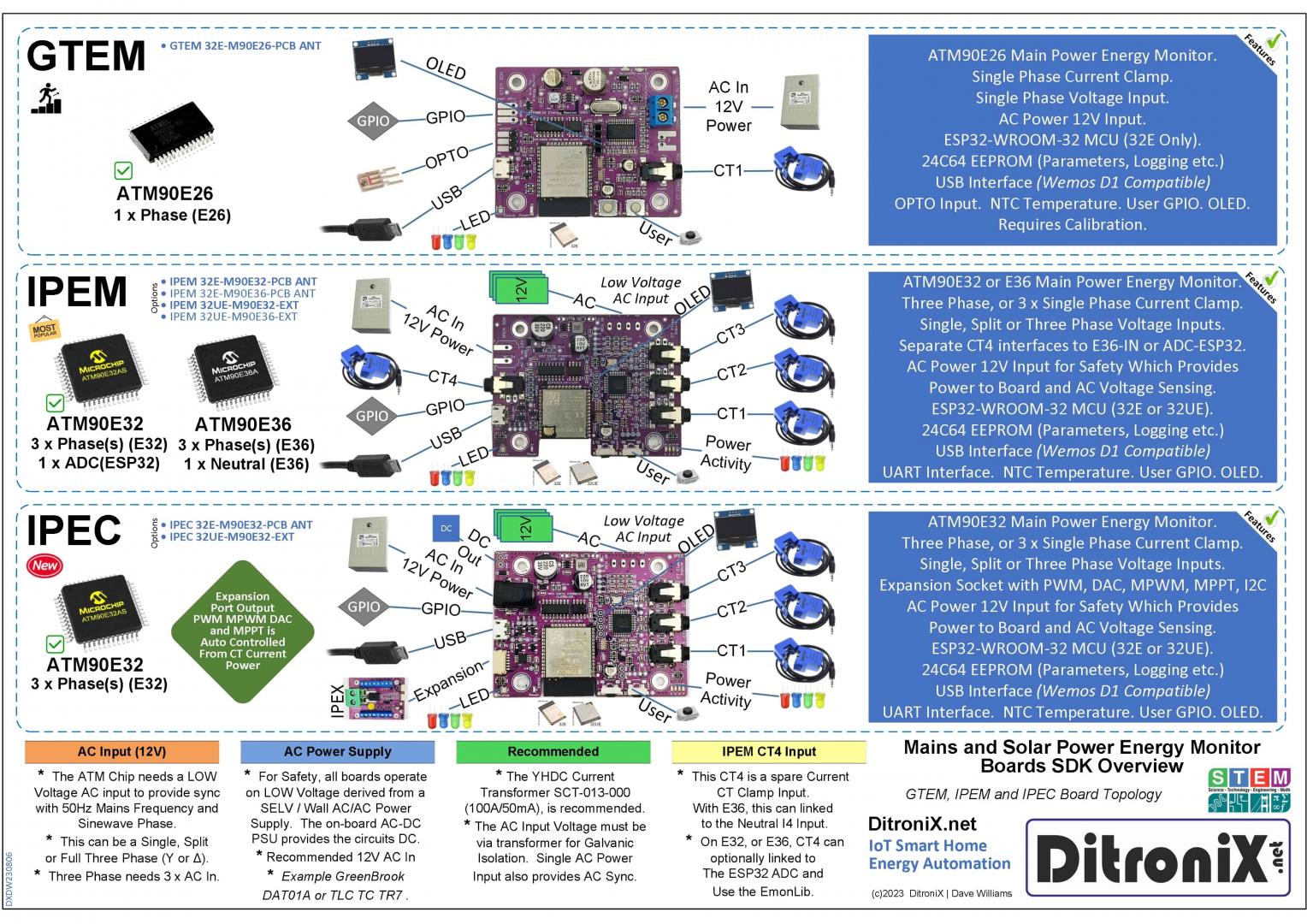
IPEM Overview

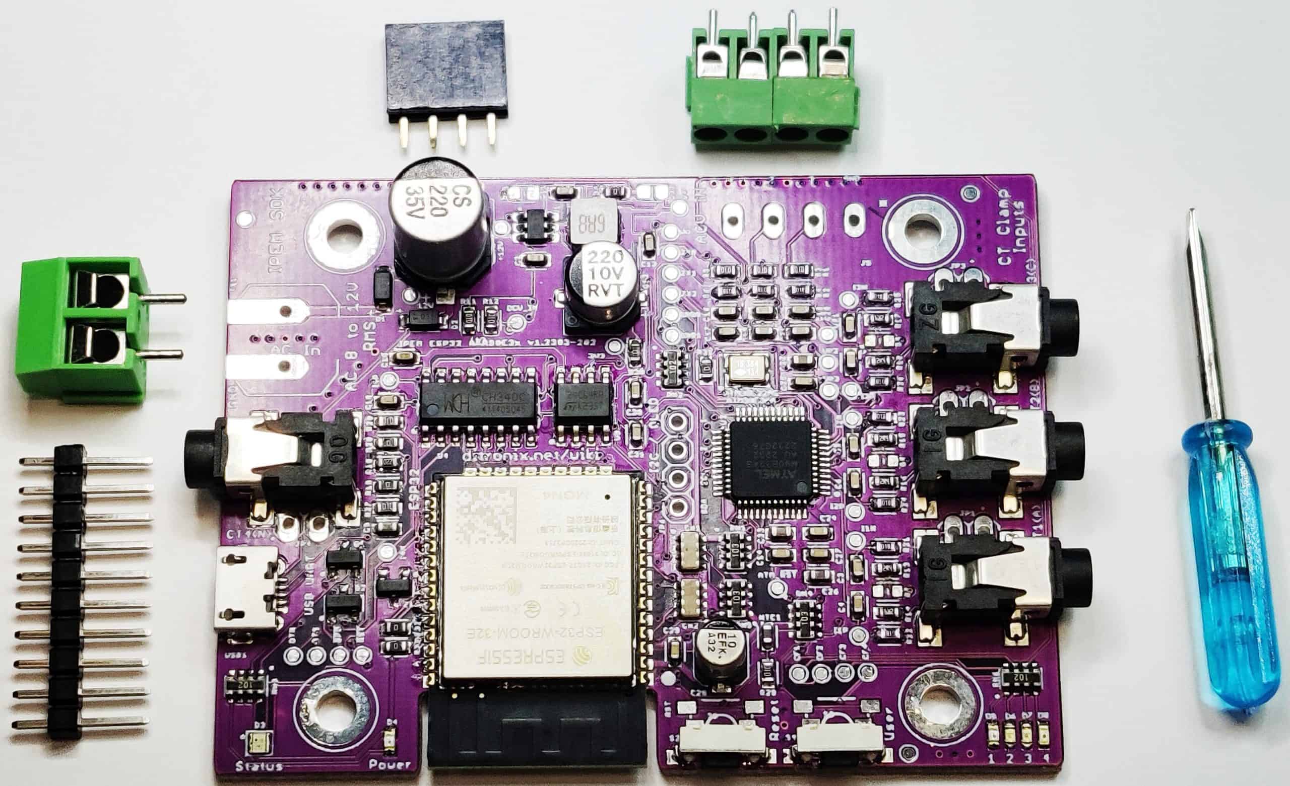
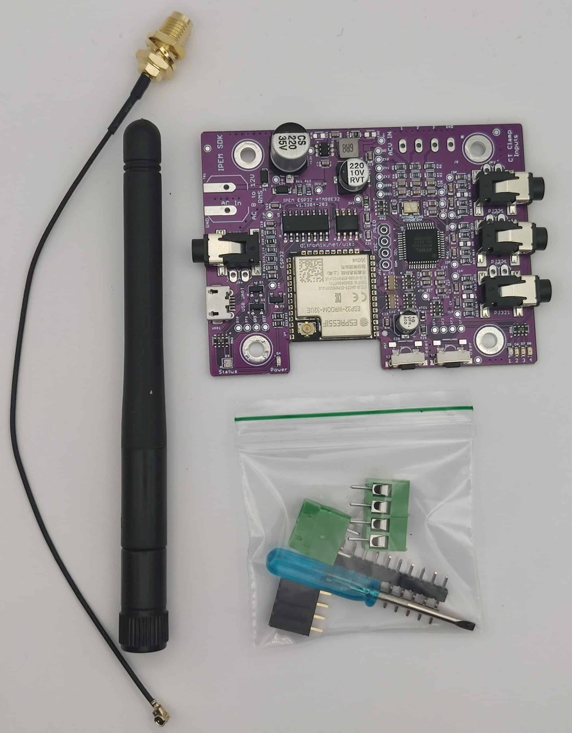
The IPEM Kit
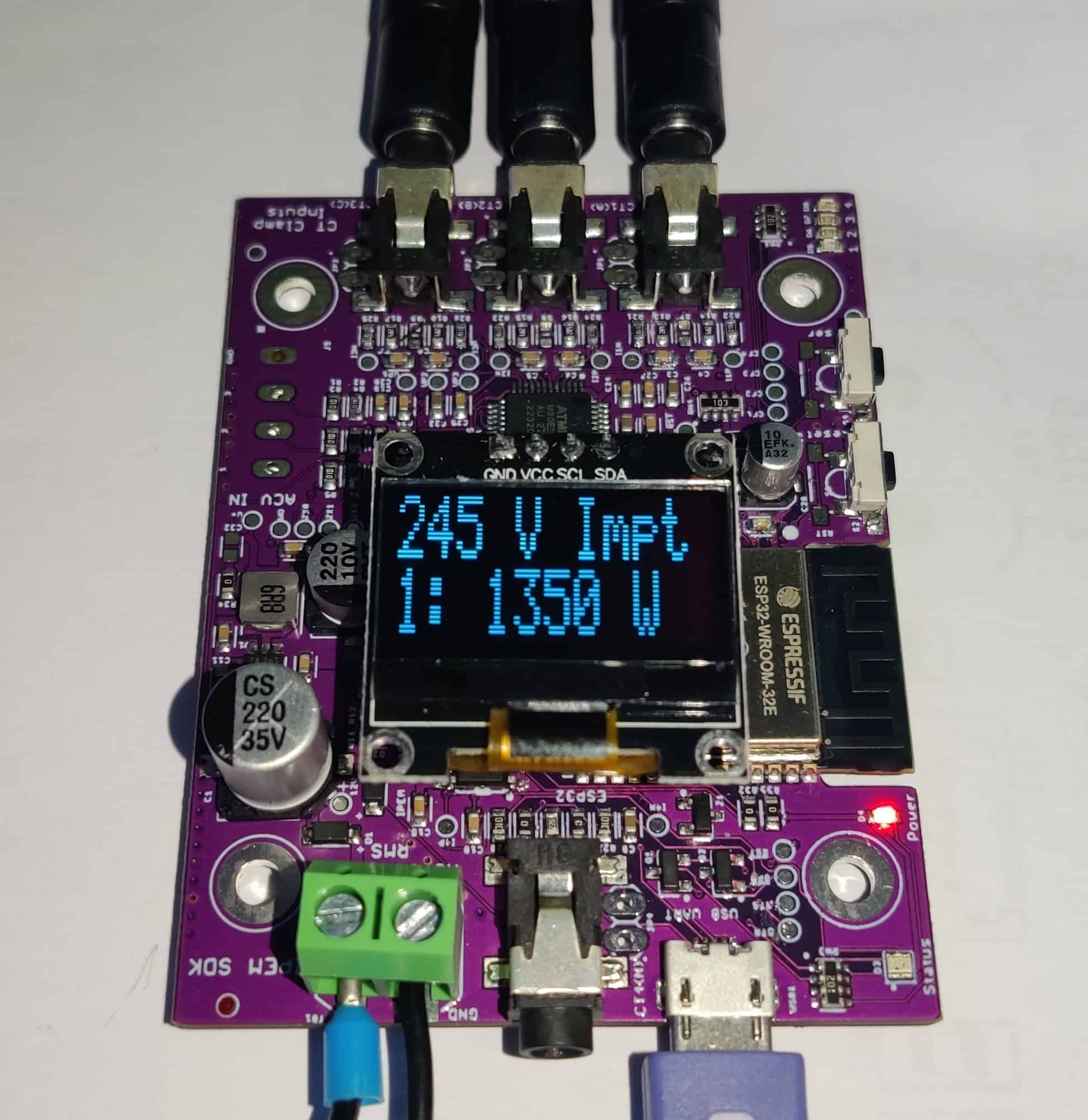
IPEM with OLED
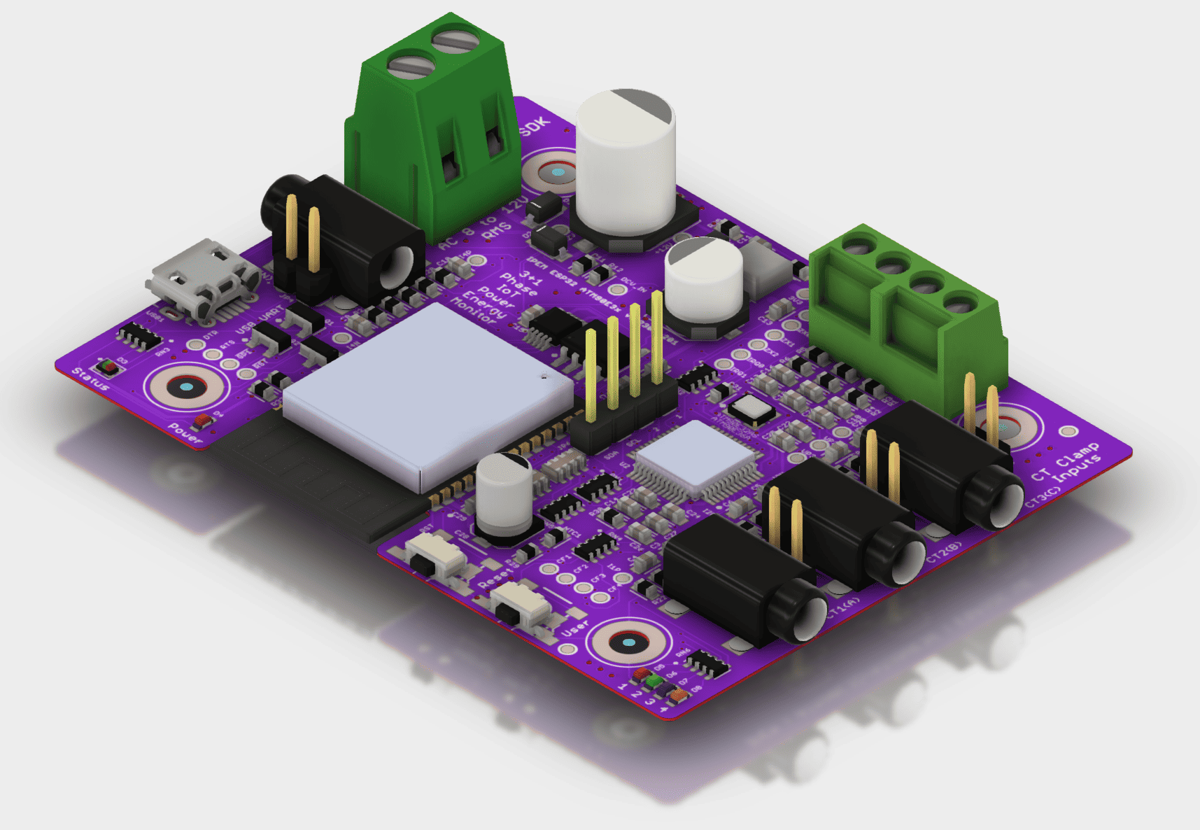
IPEM Production - 3D Render
IPEM with Integrated Push OTA Example


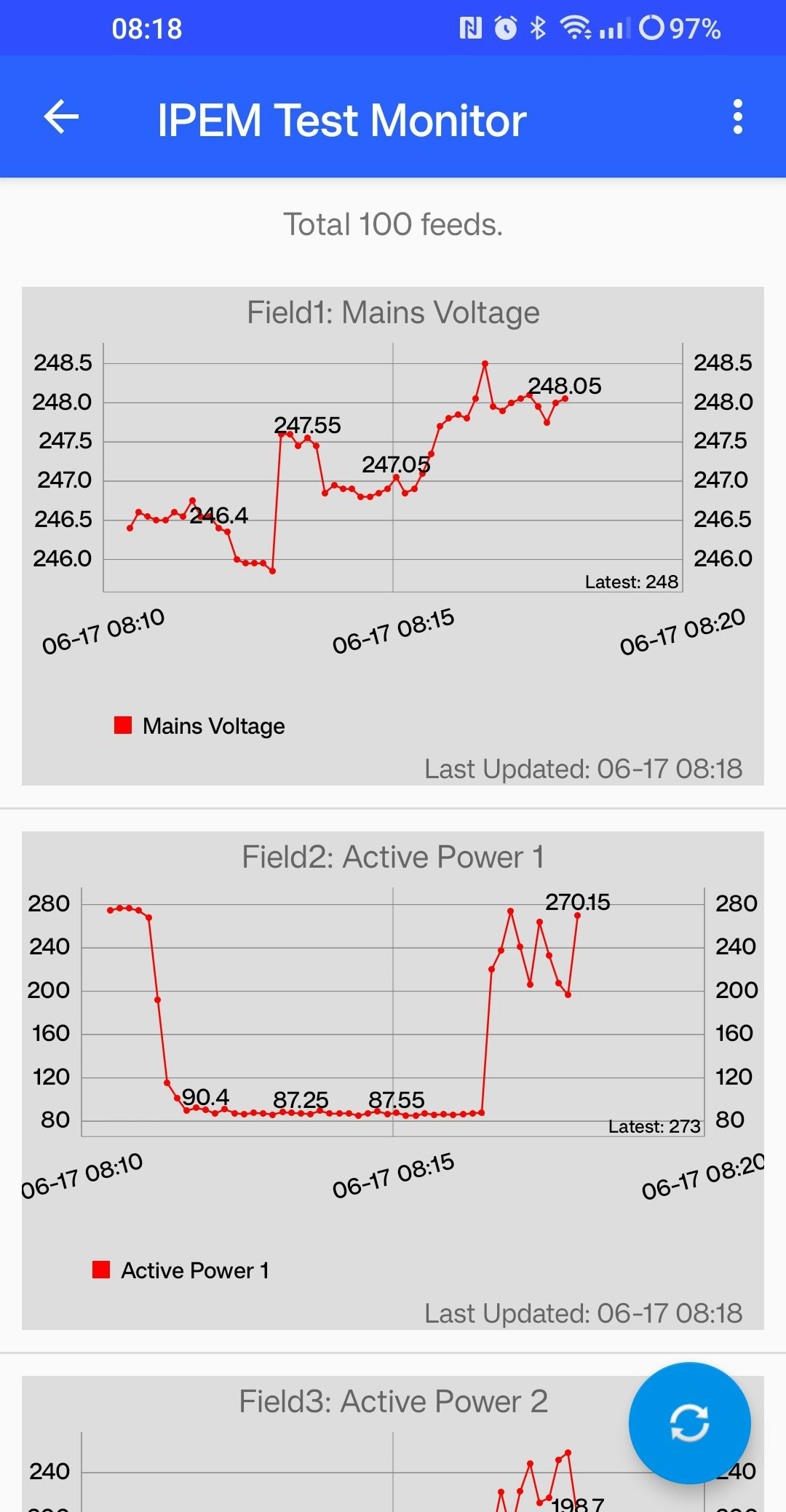
IPEM Example Real-Time Output to ThingSpeak

IPEM Example Real-Time Output to ThingSpeak into ThingChart on Mobile Phone App
Four fully tested versions of this board are available. Thye most popular being ESP32E (PCB Ant), plus ATM90E32.
The board layout is designed to be a flexible dual purpose.
- ESP32 WROOM, with Internal Antenna, or UF.L connector for external antenna
- ATM90E32 or ATM90E36
CT Clamp Inputs
The forth CT input on the ATM90E32 board, which is included for the ATM90E36, now remains on the board and goes to the ESP32 ADC. So both board variants will have FOUR CT inputs.
-
ATM90E32
-
3 x CT Line inputs to the ATM chip.
-
1 x CT input to the ESP32 ADC.
-
ATM90E36
-
3 x CT Line inputs to the ATM chip.
-
1 x CT N input to the ATM chip or CT to ESP32 ADC
-
Alternative 1 x CT input to the ESP32 ADC.
IPEM 'Production PCB

ATM90E32

ATM90E36

The IPEM IoT Power Energy Monitor board main features:
- Compact and Flexible Design SDK Board
- All connections are low voltage, for safe operation
- Easy to interface
- Optional Espressif ESP32 WROOM
- ESP32-WROOM-32E-N4
- Integral Antenna Wireless and Bluetooth
- ESP32-WROOM-32UE-N4
- Ext Antenna - U.FL Socket
- Wireless and Bluetooth
- ESP32-WROOM-32E-N4
- Optional ATM90E Series
- ATM90E32 Energy Monitor
- 3 x Phases Line CT Clamp Input
- Example YHDC SCT013000
- 3 x Voltage Inputs (AC RMS)
- Power Modes Settings
- 3 x Phases Line CT Clamp Input
- ATM90E36 Energy Monitor
- 3 x Phases Line CT Clamp Input
- Example YHDC SCT013000
- 3 x Voltage Inputs (AC RMS)
- 1 x Phase Neutral CT Clamp
- DMA Mode (Logging via SPI)
- Power Modes Settings
- Auto DMA selection opton via GP12
- 3 x Phases Line CT Clamp Input
- ATM90E32 Energy Monitor
- 24C64 EEPROM
- Parameter Settings
- Logging
- OLED I2C
- I2C Interface
- OLED I2C Connector
- Configurable Power Pins
- AC Low Voltage Input (for Safety)
- Power safely derived from a SELV / Wall AC/AC Power Supply
- 8 to 12V AC RMS
- Examples GreenBrook DAT01A or TLC TC TR7
- Power safely derived from a SELV / Wall AC/AC Power Supply
- Onboard 3V3 DC SMPS Power Supply
- Power taken from AC Input
- Arduino Wemos D1 Compatible USB Interface
- On-board Micro USB Socket
- Flashing and Programming
- Example wemos_d1_mini32
- Can also used to power the board
- Debugging
- On Board NTC (Temperature)
- USER GPIO/UART
- 2 GPIO for User (GP16 and GP17)
- UART Interfacing (UART 2)
- Reset Button
- User Programmable Button
- RGB Status LED
- User Configurable
- Power LED
- On 3V3
- ATM CT LEDs
- CF1 - Active
- CF2 - ReActive
- CF3 - Fundamental
- CF4 - Harmonic
- PCB designed to fit into an BMC enclosure
- Also allows for the display to be included, or not.
- Size 70 mm x 53 mm
In The Box
External Antenna Version
Our SDKs are WeMos D1 Mini flashing compatible Set the BOARD to ESP32, 'WEMOS D1 MINI ESP32' DEV Module (or similar). You can also set the BAUD rate to 921600 to speed up flashing. The SDK does NOT need external power to flash. It will take Power from the USB 5V. You will need to provide external 12V AC for power up of the Energy Monitor functions. You will need to provide a CT Current Clamp. Ideally YHDC SCT-013-000
All test code is OPEN SOURCE and although is is not intended for real world use, it may be freely used, or modified as needed. It is distributed on an "AS IS" BASIS, WITHOUT WARRANTIES OR CONDITIONS OF ANY KIND, either express or implied.
Additional information, and other technical details on this project, maybe found in the related repository pages.
Repository Folders
- Code (Code examples for Arduino IDE and PlatformIO)
- Datasheets and Information (Component Datasheets, Schematics, Board Layouts, Photos, Technical Documentation)
- Certification (Related Repository Project or Part, Certification Information)
Repository Tabs
- Wiki (Related Repository Wiki pages and Technical User Information)
- Discussions (Related Repository User Discussion Forum)
- Issues (Related Repository Technical Issues and Fixes)
We value our Customers, Users of our designs and STEM Communities, all over the World . Should you have any other questions, or feedback to share to others, please feel free to:
- Visit the related Project plus the related Discussions and Wiki Pages. See tab in each separate repository.
- Project Community Information can be found at https://www.hackster.io/DitroniX
- DitroniX.net Website - Contact Us
- Twitter: https://twitter.com/DitroniX
- Supporting the STEM Projects - BuyMeACoffee
- LinkedIN: https://www.linkedin.com/in/g8puo/
Dave Williams, Eastbourne, UK.
Electronics Engineer | Software Developer | R&D Support | RF Engineering | Product Certification and Testing | STEM Ambassador
Supporting STEM Learning
Life is one long exciting learning curve, help others by setting the seed to knowledge.