The iSensor SPI Buffer is a hardware and software solution designed to buffer iSensor IMU data, enabling asynchronous sampling systems (specifically embedded Linux systems) such as the Raspberry Pi, BeagleBone, Nvidia Jetson, etc. to capture IMU data at high sampling rates with accurate timestamps and without data loss. Output data is provided through a USB Virtual COM port and/or a user SPI port allowing transparent augmentation of an existing IMU interface system.
The firmware runs on an STM32F303 microprocessor to enable full-throughput, buffered IMU data capture with a variety of output data formats. An ADG1611 analog switch IC to enable routing SYNC and DATA READY signals from the host system directly to the IMU. The SPI buffer board is designed to be compatible with all current and future iSensor IMU products.
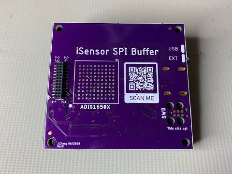
A custom PCB was designed to fit the profile and form factor of an ADIS1649x IMU. This profile allows the iSensor SPI Buffer to act as a drop-in solution for existing, high-performance solutions. The buffer interface is designed to mimic the iSensor page convention and SPI settings out-of-the box.
Additional hardware and software resources are linked below.
Python USB Interfacing Library
Firmware Documentation (Doxygen)
Software Timing Characterization
A video walkthrough and tutorial of the SPI Buffer Board's features is hosted on YouTube. Click on the image below to check it out!
This firmware is designed to operate in the STMicro processor family - specifically the STM32F303 processor. The STM32F303RET6 variant of the processor family was chosen for this application because of its large SRAM and low cost.
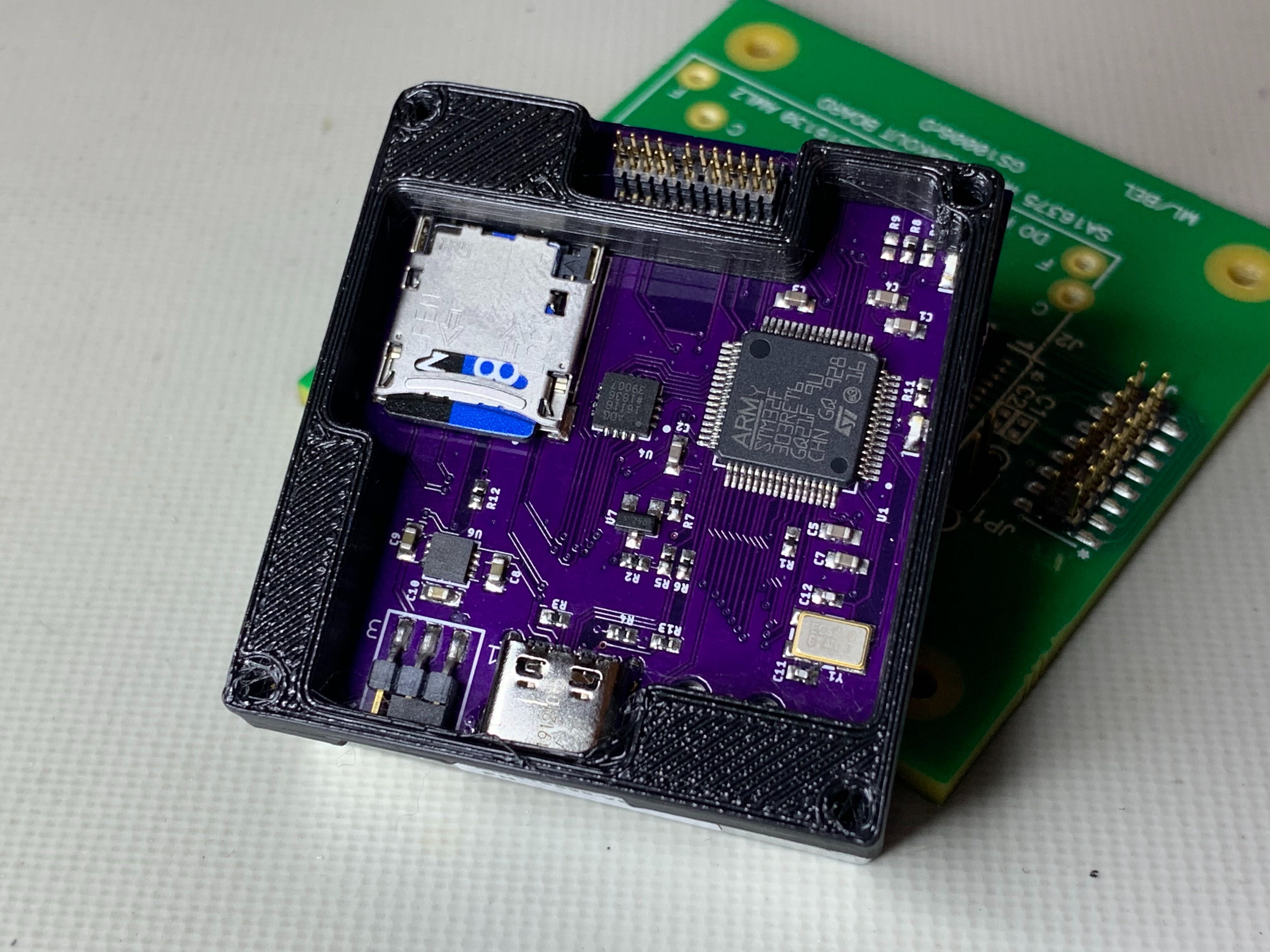
Revision B of the PCB design includes the following features:
- STM32F303RET6 processor (64k SRAM, hardware SPI peripherals, DMA fabric)
- ADG1611 analog switch - used for mapping SYNC and DATA READY signals from the IMU to the buffer board or SPI host
- ADP1706 high-transient linear regulator - used to regulate USB 5V and power both the IMU and buffer board
- Power supply selection jumper for powering the buffer board & IMU from the 24-pin IMU connector or USB
- USB C expansion port - Provides a USB virtual COM port command line interface to read/write registers and stream IMU data
- SD card slot - Allows IMU data to be captured "headless" without the use of a PC or SPI host
- LEDs - used to indicate buffer state and SPI buffer errors
- 24-pin IMU connectors - used to interface with and pass through IMU and SPI Buffer data to and from a host using SPI
- ADIS1650x footprint - used to enable the evaluation and use of compact iSensor IMUs
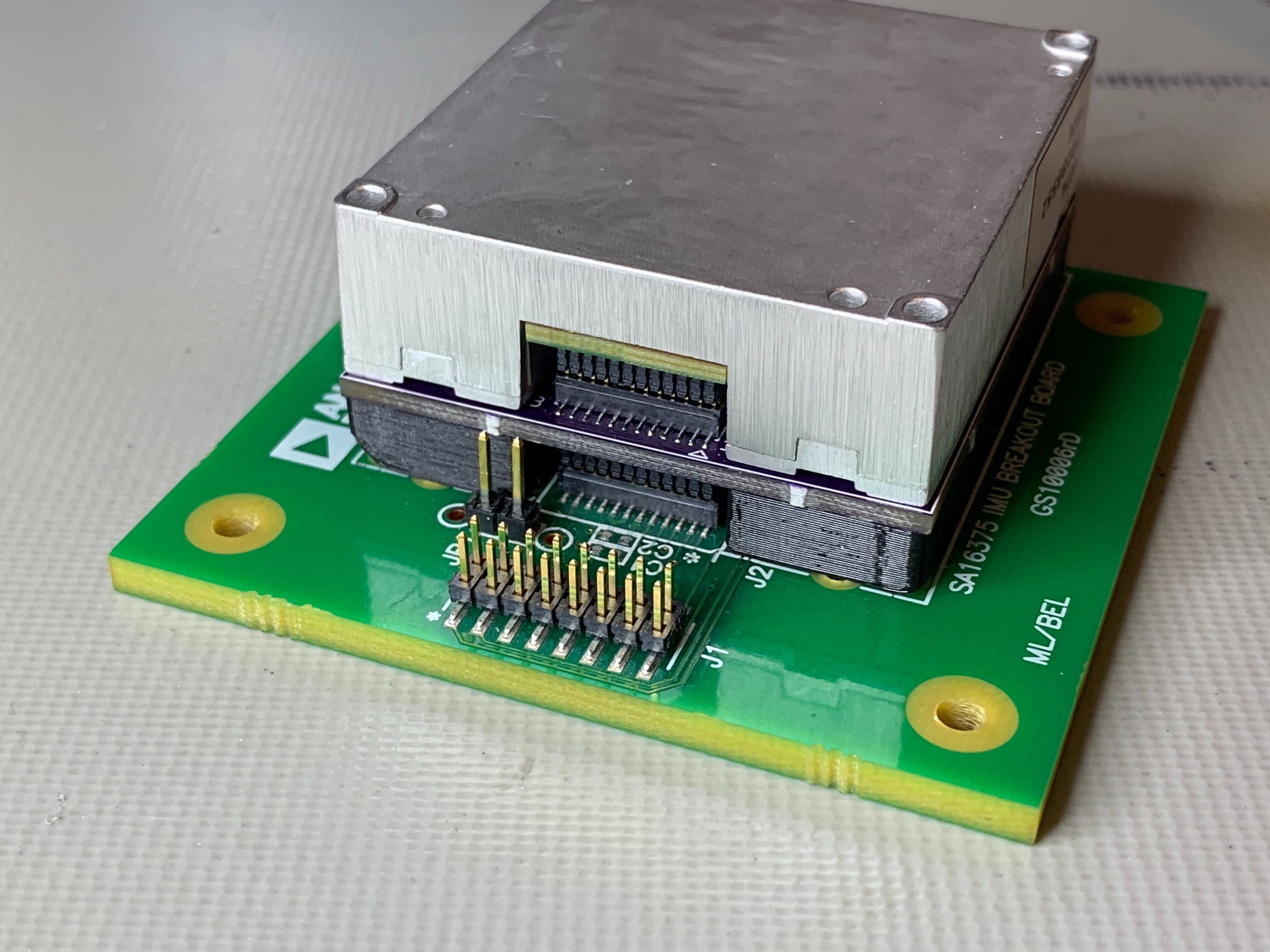
The iSensor SPI Buffer was designed to sit between an iSensor IMU and the SPI host without changing any existing PCB designs.
The code contained in this repository was developed using the freely available STM32 Cube IDE. A compatible project file is also included in this repository to make getting stared as easy as possible.
A TC2030-IDC cable must be used to interface with the SWD pads on the Rev B PCB. Development was originally done on an NUCLEO-F303RE development board. When programming a buffer board, we've continued to use the NUCLEO as the SWD programmer.
Support for the SPI Buffer Board in Linux (over SPI) was developed by spalani7. His repository is located here. For USB interfacing, the included Python library can be utilized for easy integration with any USB capable system.
- "Invisible" SPI pass-through to an iSensor IMU, including modules that implement register pages
- iSensor-SPI-Buffer configuration registers and buffered data acquisition registers will be placed on unassigned IMU pages (Pages 253 - 255)
- Autonomous IMU data acquisition will be driven by the IMU-generated data ready signal. Data will be stored in the iSensor-SPI-Buffer SRAM until retrieved by a user
- Programmable data request message (MOSI) to be transmitted after each data ready signal. Allows users to customize the register writes, contents, and order
- Programmable data acquisition length after each IMU data ready signal. Allows the user to configure the length of data read back from the IMU
- Programmable data acquisition SPI word size. The default 16-bit length provides support standard register reads, writes, and burst reads on most IMUs
- Buffer overflow setting (stop sampling vs delete oldest)
- Data ready input (from IMU) DIO number
- IMU Data ready trigger polarity
- Master SPI (interface between the iSensor-SPI-Buffer firmware and the IMU)
- SCLK Frequency
- Stall time
- Slave SPI (interface between the iSensor-SPI-Buffer firmware and the host processor)
- Standard SPI settings (CPOL, CPHA, endianness)
- Reading a buffer retrieve register will dequeue data from the buffer data structure to the buffer output registers for retrieval by a user
- The user will can clear the buffer using a control register
- A buffer counter will be added to each buffer for the user to keep track of the state of the buffer. This counter must also be accessible without dequeuing data from buffer
- Using a maximum buffer entry size of 64 bytes, the buffer will provide a minimum of 512 frames of buffering using 32KB SRAM
- STM32F303 has 80KB of SRAM available, so more than 512 entries may be feasible
The iSensor-SPI-Buffer firmware will utilize two hardware SPI ports. One operating as a master (SPI buffer to IMU communication) and the other as a slave (SPI buffer to host)
- The slave SPI port will expose the IMU register interface along with the iSensor-SPI-Buffer configuration registers to the master
- The slave SPI port will support all standard SPI configuration parameters
- The master SPI port will communicate with the IMU using the standard, iSensor SPI protocol
- The master SPI port configuration will be limited to customizing SCLK frequency and stall time
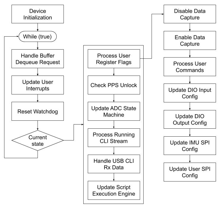
The iSensor-SPI-Buffer communications interfaces (SPI, SD card logging, USB CLI) are interrupt driven. A main cyclic executive loop handles command execution, interrupt generation, and diagnostics. The cyclic executive flow is shown below:
User SPI Interrupt
There will be an ISR to handle user-initiated SPI transactions (slave interface). If the active register page is not one of the SPI buffer pages (253 - 255) all SPI transactions will be forwarded to the IMU downstream.
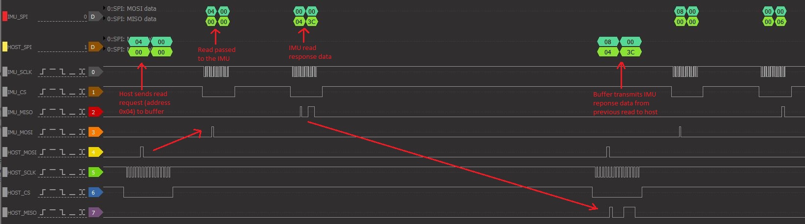
SPI transactions will be classified as "read" or "write" by the SPI buffer board the same as the iSensor IMU SPI protocol. A write operation is signaled by setting the MSB of each 16-bit word. The upper 8 bits of the 16-bit transaction contain the register address to be written to as well as the read/write bit. The lower 8 bits of the 16-bit transaction contain the data to be written.
A single read request transmitted to the SPI buffer on the slave interface will result in two SPI transactions sent to the IMU on the master interface. The first transaction sends the register read request to the IMU and the second reads the requested register contents data back from the IMU. The requested IMU register is then loaded into the SPI buffer user SPI transmit buffer so that it is available to the user on the next user SPI transaction. For write transactions, a single write command will be sent to the IMU. The data resulting from the write transaction is then loaded into the SPI buffer user SPI transmit buffer. Unlike the read operation, a write operation will not automatically generate an additional SPI transaction. The diagram below shows the IMU SPI pass-through process for a register read operation.
Autonomous Data Capture
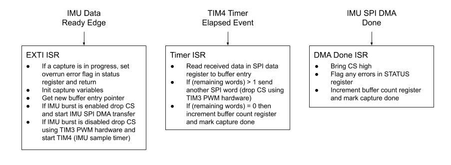
When the currently selected page is 255 (buffer output register page), the iSensor SPI Buffer firmware will begin to monitor a user-specified GPIO interrupt for data ready signals pulses. Once a data ready pulse is detected, the firmware will transmit the data contained in page 254 (buffer transmit data) in the order specified by the user. Data received from the IMU during each 16-bit transaction will be stored in a new buffer entry in the iSensor-SPI-Buffer SRAM. The firmware will use DMA and timer peripherals to perform the SPI transactions with minimal CPU intervention while giving control over the SPI SCLK and stall time.
The data capture ISR will be triggered by a user-specified GPIO, corresponding to the IMU data ready signal. The data capture ISR will configure a timer peripheral (which drives SPI word transmission timing) to trigger a DMA between memory and SPI. A DMA done ISR will handle cleaning up the DMA transactions and incrementing buffer pointers following a complete data set acquisition from the IMU. If the selected page is changed off page 255, the IMU data ready interrupt data capture functionality will be disabled (can be re-enabled by writing 255 to the page ID register on any page).
User Interrupt Signaling (to host)
Each of the four DIO lines from the iSensor-SPI-Buffer to the master device can be configured to operate in one of four modes
- Watermark Interrupt Mode: The selected DIO will go high when a specified number of samples are available to be dequeued. This allows a master device to simply monitor the data ready interrupt signal for a positive edge, and then dequeue a large number of IMU data samples
- Buffer Full Interrupt Mode: The selected DIO will go high when the buffer is full
- Error Interrupt Mode: The selected DIO will go high when an error is detected and flagged in the STATUS register
- Pin Pass-Through Mode: The DIO output from the IMU (e.g. a data ready signal or sync signal) will be directly connected to the master device, using an ADG1611 switch. When a DIO is configured in pin pass-through mode it cannot be used for interrupt signaling
The state of each interrupt signal is checked and updated on each iteration of the main cyclic executive loop. This ensures quick response time to changes in the buffer state while maintaining a simple program flow.
Command Execution
- When a write is issued the USER_COMMAND register, a COMMAND flag will be set and processed by the cyclic executive loop
- While a command is being executed, the user SPI port will be disabled, and any interrupt lines (data ready or buffer full) will be brought low
- Configuration registers for iSensor SPI buffer available on page 253
- The data acquisition write data registers (data to transmit per data ready) available on page 254
- Buffer output data registers on page 255
- Volatile output registers available on page 252
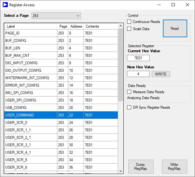
This buffer firmware includes a feature that allows the host SPI peripheral on the buffer board to be reconfigured to suit the host's needs. Because of this, it's possible to lock yourself out of the buffer board. A bad SPI configuration will usually look like the buffer board is returning the same value repeatedly for all registers. Note that the buffer board returning 0xFFFF or 0x0000 could be caused by other issues (no power to the buffer board, bad connection to the IMU, etc.) A bad SPI configuration will look similar to the image below.
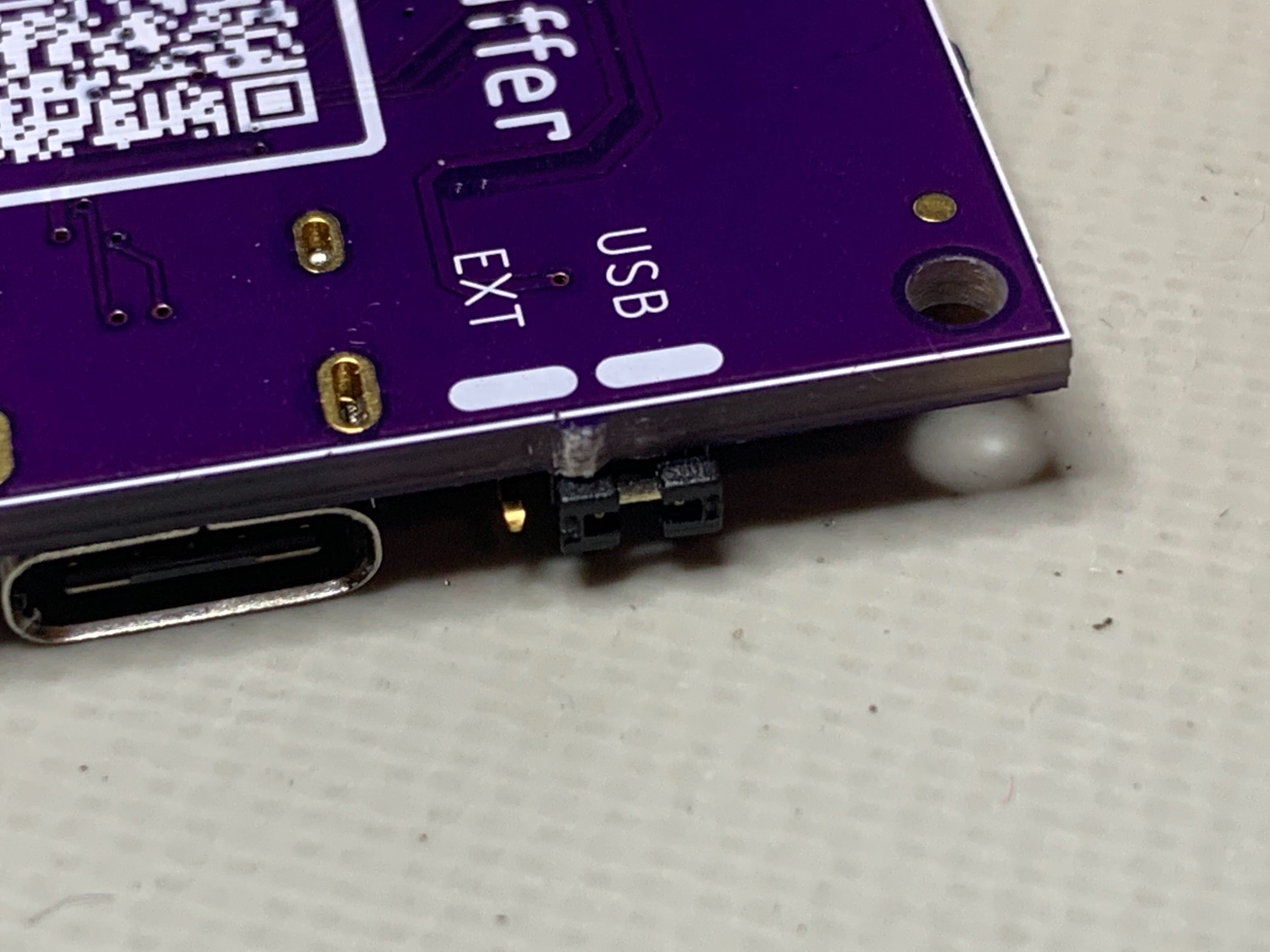
Recovering from a bad configuration requires using the USB CLI to communicate with the buffer board's firmware. While not mandatory, we recommend changing the jumper on the buffer board to USB power mode. The jumper just needs to be repositioned as shown below.
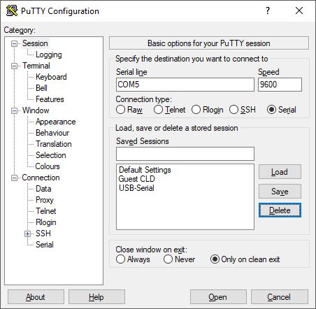
Using a terminal program such as TeraTerm or PuTTY in Windows, connect to the board using the enumerated COM port. The virtual USB port will automatically detect the host serial settings, so additional configuration is usually unnecessary.
Once connected to the CLI, you can verify that the board is communicating correctly by typing help into the console. You should see a message like the one shown below.
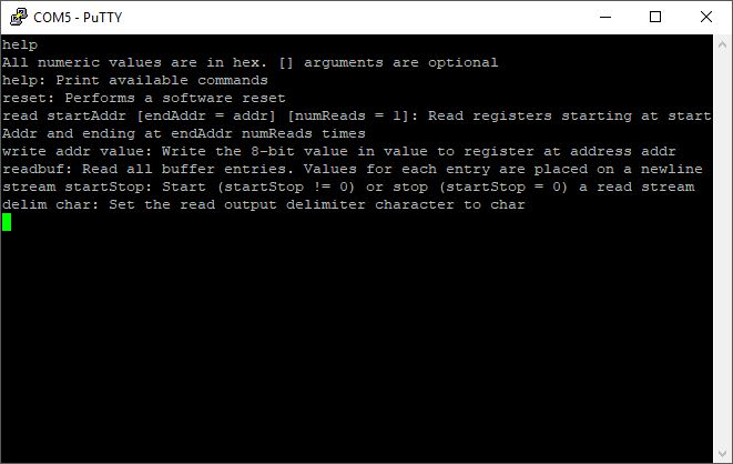
After you've verified that the CLI is working correctly, type the following command, followed by a carriage return.
freset
This will execute a factory reset command followed by a flash update command. The board should now be reset to SPI Mode 3 with CS active low. The default register settings will have also been committed to flash, so they should persist throughout reboots.
"The SPI who loved me" - PK