This document describes usage of RGB LED matrix and similar matrices.
The RGB LED Matrices are large scale panels which are the ones which are used on video walls (for example in Times Square or on the faces of skyscrapers). Essentially these are ordered rows of RGB LEDs with no driving logic or controllers on them what-so-ever. All driving and control logic needs to be implemented externally.
You can buy these on Adafruit or order directly from China. Note however that there is no uniformity or conformity in what is being sold out there. Each lot is different. Each manufacturer has his own set of ICs and driving mechanism (most use one of them). Beaware of this when your order. They're not very expensive. In general a 16x32 matrix costs about $25 in the U.S. and $10 when ordered from China.
Here is what they look like: (shown 16x32 matrix)
Front side:

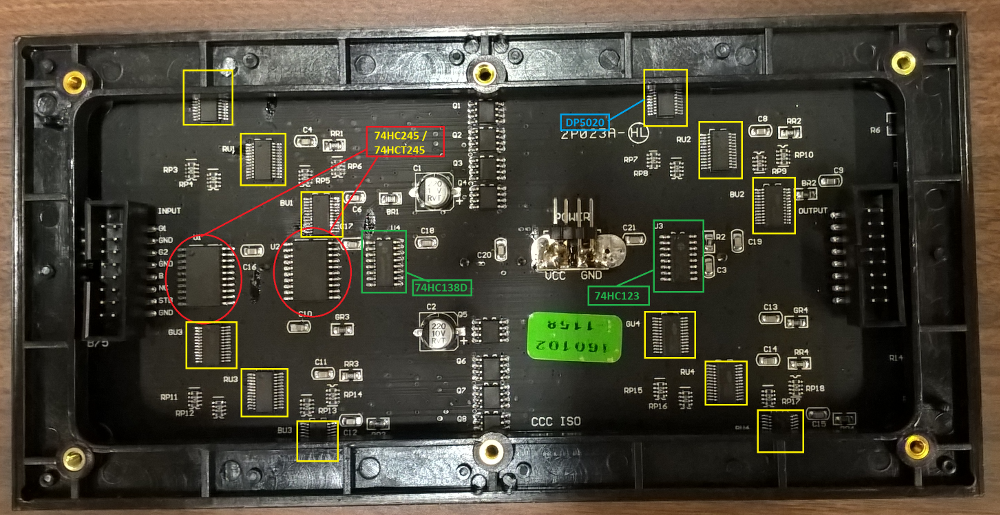
Rear side:
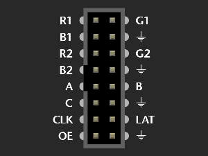
Depending on the panel height, the pinout may vary slightly. The pinout on the input is shown below (pictures from Adafruit)
16 row matrix
32 row matrix
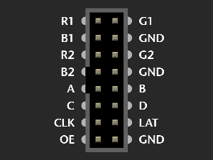
The pins are listed below with their functions:
R1  -> Red primary row
B1  -> Blue primary row
G1  -> Green primary row
R2  -> Red multiplexed row
B2  -> Blue multiplexed row
G2  -> Green multiplexed row
A   -> First address line (MSB)
B   -> Second address line
C   -> Third address line (LSB or when D exists, D is LSB)
D   -> Fourth address line (height >= 32 only). GND when height = 16.
CLK -> Clock line used to shift bits in.
~OE -> Active low line to determine of the LEDs are ON or OFF.
LAT -> Latch line to latch-in the clocked color bits for the twin-row at once.
GND -> 3 or 4 ground pins. Connect them all to ground.
Below shown is a compatible wiring used in this project. You can however modify wiring to suit your needs with the exception of ~OE -> GPIO18 because this uses PWM and it is only possible on GPIO18.
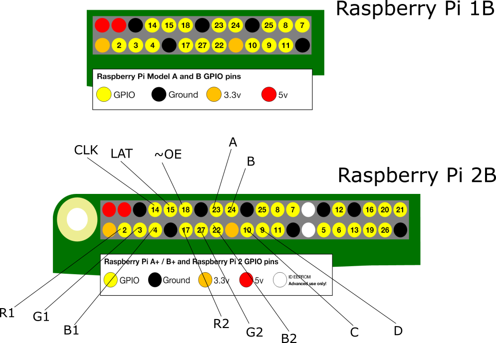
Tip: Since wiring and re-wiring can be a nightmare since there are 3 sets of numbers (Rasp Pi GPIO number, Rasp Pi pin number and Matrix input), you might want to create a custom populated connector like the one shown below:

If you're using a hat or another adapter, the need is obviated, but still I find this very very useful and time saving.
On the rear side marked out are the digital logic ICs. First, 74HC245/74HCT245 are used to buffer inputs. Depending on which one of those your panel has, you might need to add a logic level converter from 3.3V to 5V.
TTL logic, 74HCT245 can handle inputs from 2.6V to 5V as logic high and this plays well (larger input noise margins) with Raspberry Pi or other 3.3V GPIO output directly without any level converter.
However if you have the CMOS version, 74HC245, the input noise margins are pretty low so logic high is only detected from 3.5V to 5V. You most definitely need a logic level converter . You can easily build your own with 2 74HCT245s for all 12 input lines. My personal favorite method is to desolder the 74HC245 chips and solder in the 74HCT245 ones. Generally these matrices have them in SO-20 package like the one you can buy from Digikey here. If you don't want to go through this trouble, the there is also a designed adapter available here which you could print and populate yourself. Adafruit also has a full hat for this.
The other important IC on the panel is 74HC138 which decodes the row address (3:8 decoder). This is 74HC238 on 32x32 panels decoding 4:16 rows. Lines A, B, C and D (only present when height of the matrix is 32 or more) are decoded from binary to activate a particular twin row. Two rows separated by half the panel are addressed at once. Such a multiplexing reduces overall flicker than when consecutive lines are addressed together.
74HC123, which is monostable multivibrator, is used probably to reshape CLK or ~OE (I'm not sure which one it is) when forwarding to the next cascaded panel through the output connector.
The other yellow outlined ICs (DP5020) are just 16-bit shift registers. There are 12 of these on each 16x32 panel. This implies 32 LEDs x 2 Rows x 3 Channels (R, G and B) = 192 bits of possible storage at any instant of time.
Driving these panels is pretty intensive task. Each bit of each color channel has to be accurately timed to produce the desired color. This is the part I struggled to understand initially and it took me a while, so I'll try to explain this as clearly as possible.
As explained in the previous section, each address corresponds to two row separated by half the panel height. For example, if the panel is 16 rows high, then ABC = 000 corresponds to row 0 and row 8 together. Let's call this a twin-row for all future references. Similarly for 32x32 panels ABCD = 0002 corresponds to row 2 and row 18. The top (primary) row receives color data from R1, G1 and B1 lines while the bottom row (multiplexed) receives data from R2, G2 and B2 lines.
So for each clock cycle, 6 bits are shifted in (one of R/G/B(1) and R/G/B(2)). So to clock in a twin-row it takes width number of clock cycles. 32 clock cycles for one 16x32 Matrix for example. If cascaded, one twin-row corresponds to the full cascaded width. For example if you cascaded 3 panels of 32 LED width each, then your twin-row will be 96 bits wide hence taking 96 clock cycles to shift in. Remind you that clocking a full twin-row corresponds to just one bitplane, i.e, just one bit of R/G/B of 8-bit color.
Now, how does this show the required color? This is where timing and weighting kick in. Each bitplane of color needs to be held after latching for proportional amount of time. Since each bit of a binary number has a weight of power of two, that'll be amount of time for which it is held. For example if bit-0 is held for 0.125us, then bit-1 is held for 0.25us, bit-2 for 0.5us and so on. This needs accurate timing else hues will smudge in. Hence we use PWM.
Drive procedure:
Step 0: Start
Step 1: Set twin-row address on A, B, C, D
Step 2: Put a bitplane of corresponding row pixels on R1, B1, G1 and R2, B2, G2
Step 3: Drive CLK from LOW->HIGH (rising edge)
Step 4: Drive LAT from LOW->HIGH (rising edge)
Step 5: Drive ~OE LOW
Step 6: Wait for bitplane weighted time
Step 7: Drive OE HIGH
Step 8: Go back to Step 2 to output the next bitplane (until all bitplanes)
Step 9: Change A, B, C, D to select the next twin-row (until all rows)
Step 10: Go back to Step 0 and start over
Below is a logic analyzer capture of clocking in one twin-row for 8-bit planes (8-bit color).
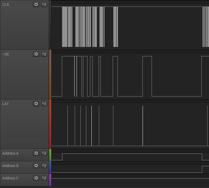
Observe how different bitplanes are held for different times. The overlapping of clocking in during hold time is an optimization.
The organization and architecture of the developed driver is shown in the figure below. rgb-matrix acts as the launch pad for maintaining threads and wrapping internal structure.
The driver runs three threads. The main controller thread (Main-Thread), a pixel driving color pump thread (Pix-Driver) and the frame buffer maintenance thread (What-Thread). The main thread spawns the other two threads and waits until a termination is requested. It can handle user inputs or monitor an event.
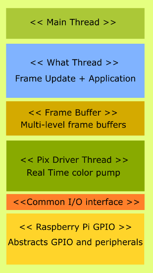
To develop an application of to play with what is shown on the matrix all you need to do is fill pixels of the frame buffer in what::playground(). Every true return changes the active frame buffer to the newly filled one.
Frame buffer provides a mechanism of multi-stack buffers which can be filled in parallel when Pix-Driver is updating the matrix. Currently this is double-buffered, but can be easily extended to something bigger like a circular buffer by modifying FRAME_BUFS parameter and changing the mechanism of switching buffers.
The interface is separated as I plan to move this code to other boards very soon. Since the interface is abstracted in rgb_mtrx_ifc.h, only this file needs to be changes for adaption to other hardware. All Raspberry Pi specific stuff is in rasp_pi_gpio class.
Futhermore, some helper classes are used to accomplish some tasks like parsing PPM files (ppm_parser) and loading and holding fonts (glyph_loader and fontizer).
To develop an application of to play with what is shown on the matrix all you need to do is fill pixels of the frame buffer in what::playground(). Every true return changes the active frame buffer to the newly filled one. A new class can be build around this, if the driving operation is specialized and complex.
Using is made pretty straightforward by exposing the full frame buffer in what::playground(). Applications themselves go in the file matrix_appl.cpp. Keep main() minimal as is. There is really no need to modify it unless you're doing some really one time global operation. You can build a class/abstraction around what class to accomplish your needs.
Note: You'll need GCC version >= 4.8.2 to build this project
The default setting is for Raspberry Pi 2. If you're using Raspberry Pi 1, then make the below changes
In rasp_pi_gpio.h comment the RASP_PI_2 flag to compile for Pi 1.
//#define RASP_PI_2        1
Usage:
- To compile the code simply use the already built
Makefile. - You can add additional files needed to it under the
src section. - Just clone this repository using
git cloneand type in"make"in the main directory. - This compiles and links to an executable named
matrix_appl. - To run you'll need
sudorights. So, type insudo ./matrix_appland you should see your matrix light up if connected correctly.
You're free to build more examples and extend this library with more features. Just open a pull request or an issue as you go on and I will take a look at them.
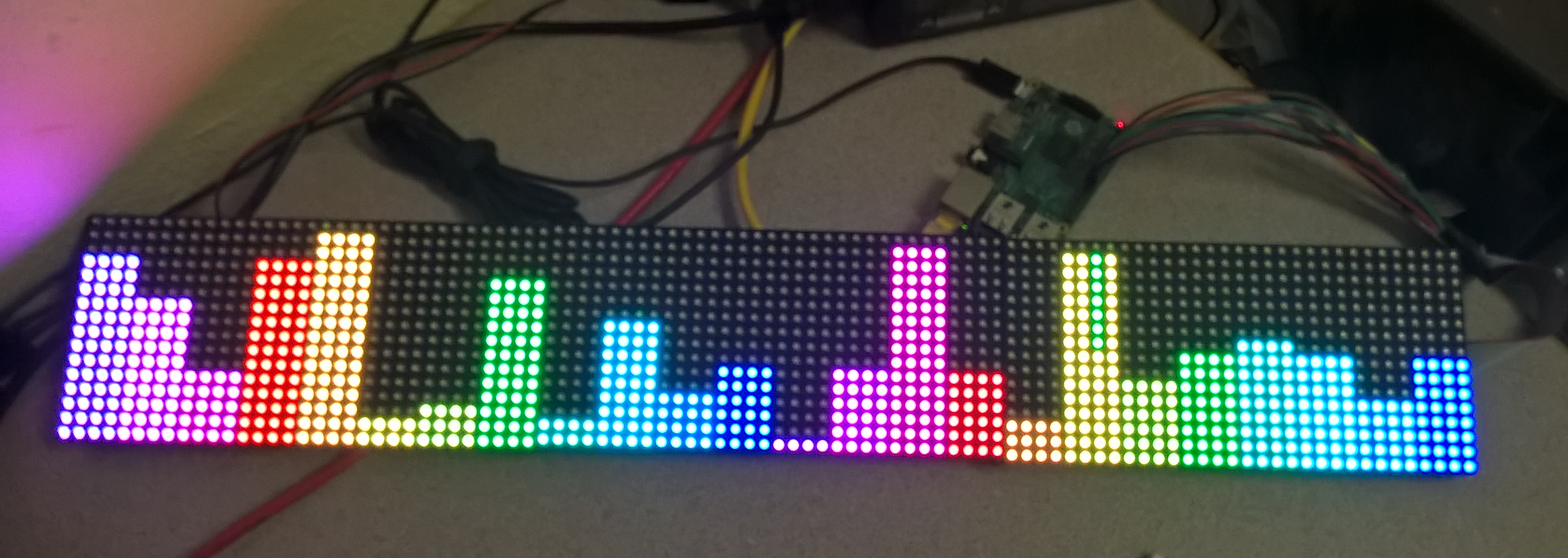
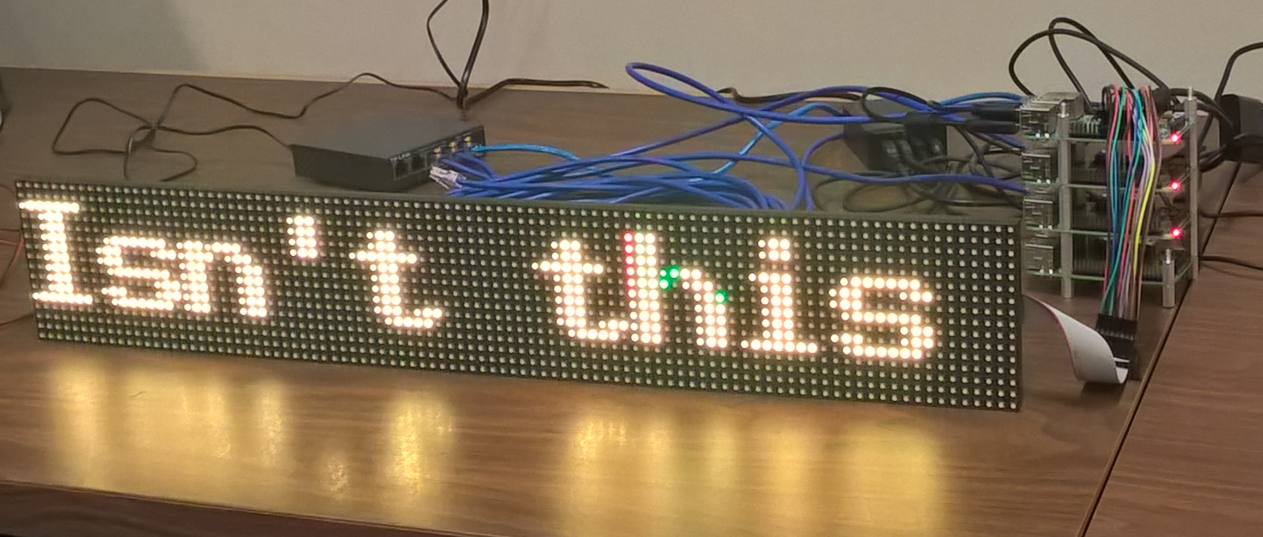
Here are some bright examples on 3 cascaded 16x32 matrices.
Random Equalizer Bars:
Scrolling dynamic text:
Thanks to hzeller for his work, I had some way of verifying that my panels were ok and indeed learnt quite a bit from his code base. Some parts of this repository have been influenced by his nice ideas of driving the display. The very first time I got these panels in my hands, I ran some of his demos and was impressed by the colors on these displays. So impressed that I decided to write my own :).