BadUSB cable based on Attiny85 microcontroller (documentation, gerbers, design and schematic).
![]()
Idea: Joel Serna & Ernesto Sánchez
Development and implementation: Joel Serna & Ernesto Sánchez
PCB design: Rev0: Jorge Mata, Rev1, Rev2, Rev3, Rev3.1: Ignacio Díaz Álvarez
The developers and collaborators of this project do not earn money with this. You can invite me for a coffee to further develop Low-Cost hacking devices. If you don't invite me for a coffee, nothing happens, I will continue developing devices.

New repository for the final version with the data line enabled: https://github.com/joelsernamoreno/EvilCrow-Cable
For Sale at:
Summary:
- History
- Acknowledgement
- Electronic components
- BadUSB Cable without USB connector
- Rev0 (only for reference)
- Rev1 (only for reference)
- Rev2 (final version)
- Rev3 (final version, this version is easier to weld on a mobile cable)
- Rev3.1 (final version, Holes D+ and D- removed)
- Information
- Rev0 (only for reference)
- Rev1 (only for reference)
- Rev2 (This version has a smaller size than Rev3)
- Rev3 (This version is easier to weld on a mobile cable)
- Rev3.1 (Holes D+ and D- removed)
- Import the project
- Introduction
- Assembly, bootloader and testing
- Pinout Rev2
- Pinout Rev3
- Pinout Rev3.1
- Hardware need to burn the bootloader
- Download bootloader
- Burning bootloader
- Assemble Development Kit
- Basic requirements
- Installation of Digispark USB Driver (Windows)
- Installation and update of Micronucleus Windows (not tested)
- Installation and update of Micronucleus Ubuntu
- Upload Payloads
- Payloads
- VM for dummies
- Start of the project and first BadUSB cable on breadboard (November 2017):

- First BadUSB cable with USB connector (December 2017):


- Finished proof of concept (January 2018):

- Technical presentation of BadUSB cable and first PCB design (Rev0) presented at Hackplayers Conference (February 2018):


- Rev1 of BadUSB cable design (January 2019):

NOTE: More information in Rev1 section.
- Rev2 of BadUSB cable design (May 2019):

NOTE: More information in Rev2 section.
- First PCBs (July 2019):


- BadUSB Cable Rev2 (August 2019):


- Rev3 of BadUSB cable design (September 2019):

- Development kit (September 2019)

- BadUSB Cable Rev3 (September 2019)

- Development kits and complete cables for Navaja Negra Conference (October 2019)

- Rev3.1 of BadUSB Cable design (October 2019)
This version is a solution for Rev3. Rev3 has the holes D- and D+, these holes should NOT be soldered and Rev3 can be confusing. In Rev3.1 design these holes are eliminated, only VDD and GND are available. Thanks to @MG for recommending this solution.

PCB design first version: Jorge Mata & Innovart
* Jorge Mata: @jor_mata

* Innovart: @innovart_cc

* https://innovart.cc
PCB design final version: Ignacio Díaz & ForensicSecurity
* Ignacio Díaz: @Ignacio Díaz Álvarez

* Forensic & Security: @ForensicSec

* https://forensic-security.com
Rev0:
- ATTINY85 microcontroller
- 2 x 3.6V zener diode
- 2 x 68 ohm resistor
- 1 x 1.5k resistor
Rev1-Rev2-Rev3-Rev3.1:
- ATTINY85 microcontroller (8-soic)
- 1 x 3.6V zener diode common anode (SOT23)
- 2 x 68 ohm resistor (0402)
- 1 x 1.5k resistor (0402)
Electronic components have been bought in: https://www.digikey.com/
NOTE: This Rev0 is included for reference purposes only, Rev2 is the final and full tested version.
NOTE: This Rev1 is included for reference purposes only, Rev2 is the final and full tested version.

Implementation of BadUSB cable based on Attiny85 microcontroller. This version has a smaller size than Rev3-Rev3.1


This version is easier to weld on a mobile cable.

This version is a solution for Rev3. Rev3 has the holes D- and D+, these holes should NOT be soldered and Rev3 can be confusing. In Rev3.1 design these holes are eliminated, only VDD and GND are available. Thanks to @MG for recommending this solution.

There is a custom built library footprints for this project, remember to import it.
You can order the necessary components with the gerber files in the gerber directory and de BOM (Bill Of Materials).
- Black: GND
- Green: D+
- White: D-
- Red: VDD

- Black: GND
- Green: D+
- White: D-
- Red: VDD


- Black: GND
- Green: D+
- White: D-
- Red: VDD


NOTE: If you have a development kit or a complete cable obtained in Navaja Negra Conference... it is not necessary to download and burn the bootloader, continue with the following steps!!!
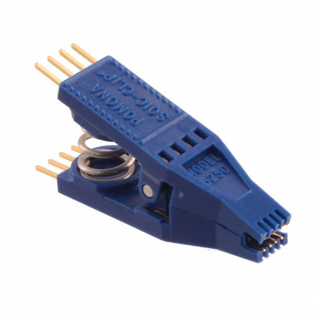
To burn the bootloader you can use diferent techniques, for the one we use you will need:
- TEST CLIP SOIC 8 (2 X 4)
- TINY AVR PROGRAMMER

-
Download Micronucleus bootloader for ATTINY85: https://github.com/micronucleus
-
You can find the bootloader file at micronucleus\firmware\releases folder
-
Use "t85_default.hex" for the bootloader (Release 2.04)

You must use the correct fuses bit for the bootloader:
- Extended: 0xFE
- High: 0xDD
- Low: 0xE1
AVRISP MKll In System Programmer and AVR Studio software for burning bootloader

- Development kit

- Add tin on the VDD pin of the USB connector

- Insert the PCB as shown in the photo

- Add more tin on the VDD pin of the USB connector

- Add tin on all pins of the USB connector (GND, D+, D- ...)

- Take a mobile phone cable and cut the male USB connector. Then you have to strip the wires as shown in the photo. NOTE: STRIP CABLES VDD and GND ONLY!!!

- Add tin to VDD and GND pins.

- Welding the VDD and GND cables to the VDD and GND pins on the PCB. NOTE: Pins D+ and D- are free, you don't have to weld this!!!


- Add adhesive tape for compact cables and a robust result


- Update Ubuntu packages with the following commands:
- sudo apt update
- sudo apt upgrade
- Download Arduino IDE: https://www.arduino.cc/en/Main/Software
- Install drivers (Windows): https://raw.githubusercontent.com/digistump/DigistumpArduino/master/tools/micronucleus-2.0a4-win.zip
- Install libusb and lib32stdc with the following commands:
- sudo apt install libusb-dev
- sudo apt install lib32stdc++6
- Install build-essential with the following command:
- sudo apt install build-essential
- Download DigisparkKeyboard library with multiple layout support: https://github.com/ernesto-xload/DigisparkKeyboard
- Unzip library in Arduino/libraries/directory
- Edit DigiKeyboard.h file and uncomment #define kbd_es_es
- Change #define kbd_es_es for your keyboard layout and save the changes
- Run Arduino IDE with the following commands (NOTE: Don't install the Arduino IDE, just run it!)
- cd arduino-1.X.XX-linux64/arduino-1.X.XX/ (example: cd arduino-1.8.10-linux64/arduino-1.8.10/)
- ./arduino (NOTE: Do not run the Arduino IDE with root permissions!)
- Click File and then Preferences
- Add the JSON URL to the Additional Boards Manager text box: http://digistump.com/package_digistump_index.json
- Click OK
- Click Tools > Board > Board Manager
- Search and Install: Digistump AVR Boards
- Close the Arduino IDE
- Download Arduino for Digispark which come with USB driver: http://sourceforge.net/projects/digistump/files/
- Extract the file (DigisparkArduino-Win32-1.0.4-March29.zip) to any folder
- Execute DigisparkArduino-Win32\DigisparkWindowsDriver\InstallDriver.exe to start installing the USB driver
https://github.com/micronucleus/micronucleus
- Create the 49-micronucleus.rules file in the /etc/udev/rules.d/ directory.
- Copy the contents to the file you just created: https://github.com/micronucleus/micronucleus/wiki/Ubuntu-Linux
- Reboot the computer or run the following command to update the UDEV rules: udevadm control --reload-rules
- Download Micronucleus with the following command: git clone https://github.com/micronucleus/micronucleus.git
- Access the micronucleus/commandline directory with the following command: cd micronucleus/commandline
- Compile with the following command: make
- Access the .arduino15/packages/digistump/tools/micronucleus/2.0a4 directory with the following command: cd ~/.arduino15/packages/digistump/tools/micronucleus/2.0a4/
- Create a backup of Micronucleus with following command: mv micronucleus micronucleus.old
- Copy the latest version of Micronucleus to this directory with the following command: cp ~/PATH/micronucleus/commandline/micronucleus .
- Reboot
- Download payloads: https://github.com/joelsernamoreno/badusb_examples/tree/master/attiny85_digispark
- Run Arduino IDE with the following commands (NOTE: Don't install the Arduino IDE, just run it!)
- cd arduino-1.X.XX-linux64/arduino-1.X.XX/ (example: cd arduino-1.8.10-linux64/arduino-1.8.10/)
- ./arduino (NOTE: Do not run the Arduino IDE with root permissions!)
- Open Payload with Arduino IDE
- Click tools and select Board: Digispark (Default - 16.5 Mhz)
- Click Upload
- Connect the BadUSB cable when the Arduino IDE says to connect it.
Demo video: https://twitter.com/JoelSernaMoreno/status/1181296289323130882?s=19

You can get payloads in the following repository:
https://github.com/joelsernamoreno/badusb_examples/tree/master/attiny85_digispark
- Download VM: https://mega.nz/#!dtBmgQIY!4iiRBmrM1v42V-EDzVBr9dvOznbAHK-9jp3wK9BgMlo
- Download and install VMWare: https://www.vmware.com/
- Run VMware
- Import Ubuntu.ova
- Install VMWare-Tools: https://vitux.com/how-to-install-vmware-tools-in-ubuntu/
- Add serial port with the following steps:
- Click on VM -> Settings
- Click on +Add...
- Select serial port
- Click on finish

- Add USB controller with the following steps:
- Click on VM -> Settings
- Click on +Add...
- Select USB controller
- Click on finish

- Run Ubuntu VM
- Enter password (password: evilcrowcable)
- Open a terminal (CTRL+ALT+T)
- Run Arduino IDE with the following commands:
- cd arduino-1.8.10-linux64/arduino-1.8.10/
- ./arduino (NOTE: Do not run the Arduino IDE with root permissions!)
- Open a payload /home/evilcrowcable/attiny85_digispark/
- Click tools and select Board: Digispark (Default - 16.5 Mhz)
- Click Upload
- Connect the BadUSB cable when the Arduino IDE says to connect it.
Demo video: https://twitter.com/JoelSernaMoreno/status/1181296289323130882?s=19