This is a demonstration of sliding plate logic, as used by Konrad Zuse in his Z1 computer. It can be made out of laser-cut acrylic and M3 nuts and bolts.
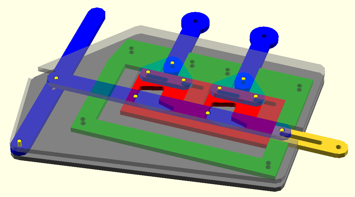
The inputs to the gate are the two rods on top. These can be pushed upwards (1) or downwards (0). To run a 'clock cycle', the lever on the left should start in the centre, vertical position. It is then pushed fully left and then fully right, then returned to vertical. The output rod on the right will be returned to zero initially, and then pushed right if the output is 1.
Some features of this design:
-
It has gain. The output rod's movement is powered both in the 0 and 1 positions and it is powered entirely by the clock lever. It requires less power on the input than it provides on the output - which is necessary if you want to chain several gates together. Note that the output is not locked in place, and could be backdriven.
-
Inversion is free on the inputs. By inverting the pattern on either or both of the red sliding gates, the inputs can be inverted. This can turn the OR gate into a NAND gate, for example. It would need more modifications to make an AND gate, but these can be made by chaining two gate units together instead.
There are two top-level files for use in OpenSCAD. orgate-assembly.scad is a 3D mock-up of the results of laser-cutting this device. orgate-laserlayout.scad is a 2D layout of all the parts to be laser cut. This will need some manual rearrangement.
The 3D layout, orgate-assembly.scad, can be seen working using OpenSCAD's animation function.