Liftoff! #11
Comments
|
Intended LC changed to 110. |
|
Generally speaking: For the model to be in equilibrium, an appropriate acceleration must be applied in the direction opposite the applied thrust, or vice versa. The "reacted" value (either thrust, or acceleration) will be shown in italics. Let's create a Loads Table for DLL Liftoff. This is all made-up, and rationale should be provided.
WC 120: Empty Starship Note: Still WIP, this table and comment will be updated. |
|
Another complication which must be addressed when creating balanced loadcases is the weight application. Currently, the material used has a density provided, and an acceleration applied overall will NOT result is the balanced state we determined mathematically. To balance this, additional mass elements must be provided, representing the difference in discretely modeled mass, and total mass for each loadcase. Mass elements should be applied where it makes sense (ie 1 mass element at each modeling station of a propellant tank, with the mass equal to the propellant portion, or payload mass tied to a payload adapter plate). Again, this is a very crude way to account for mass, but it's the best option for simplicity to get a balanced loadcase. |
|
Hey great project! I'm interested in understanding what you do here. Could you clarify your the loadcases to me? Especially the table above. Which flight scenarios do want to model and how are you applying those loads? |
|
Oh, hello! One of my next goals for this project is going to be figuring out an easy way to display and communicate loadcases. It's rather difficult... What I'm doing in this issue is only loadcases related to liftoff (and right now just from Earth). I originally thought max payload and full thrust from SH would be the worst case, but I decided last night to tabulate a couple different weight and thrust conditions above. So WC just stands for weight condition. Right now I'm only talking about the total mass in 1G, but later on it could also encompass shifting CG's. Dynamic pressures are zero, because the vehicle hasn't started to move yet (the moment right after the launch clamps release). Thrust I'm varying as stated in the comments, but since it's attached to SH, the thrust is applied to Starship through the interstage ring (the skirt that physically connects it to SH). I need to do some digging on F9 2nd Stage to see if this is accurate. I suspect it's not. It would make sense to tie in the Raptors to the SH, since the vehicle is already designed to use that thrust puck. Does any of that make sense? I'm not sure what your background is, but I'm happy to explain as much as you want. |
|
Okay, so for the start just the wet mass with acceleration at liftoff and the pressure load in the tanks. I'm interested in seeing the contour plots and reactions forces for plausibility. Can you post those here? So for a evaluation of the citical loads are you planing to model a maxQ loadcase? would be great to see the loads changing over time during the throttle down and maxQ event. Are you sure that the thrust from the Superheavy Booster is just transferred over the skrit? That would be a massive load for the rather thin interstage. During F9 livestream you can see that there is some thing like a tripod attached to the booster. Maybe that is the case with starship too.
Thanks for your explaination so far! |

|
I think you're correct about the thrust application. When I get back to working on this (hopefully next week), I'm going to tie in the engine mount nodes, and the interstage skirt nodes with an RBE3, and apply total thrust for liftoff across all of them from a separate point. I'll post some pictures of the mesh and setup once I've got it dialed in. Currently, the only loadcase I have is a static 1g droop on the pad, with tank pressure. There's no fuel mass modeled, though. I have another issue discussing hydrostatic pressure. Working out how to balance all the forces and the constantly-changing weight condition are the really difficult parts of this project. It's one of the reasons I kinda left it dormant for months. I do plan to model a max q case, once I've got the liftoff cases. And if I can write a script to apply all the mass, thrust, and acceleration loads, I'll do max q at multiple weight and thrust conditions. |
|
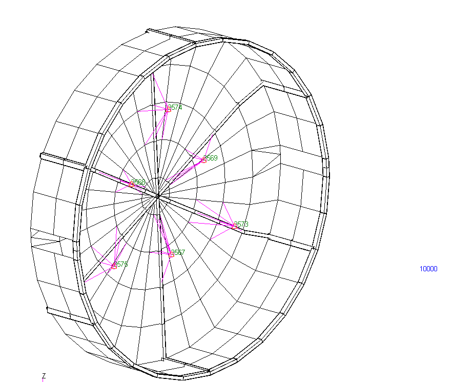
Okay so I've still got some more work to do on golden grids. I'll probably make a new issue for those, so they can be documented in detail. For starters, I made the "thrust node" with id 10,000. This node is where thrust during ascent (prior to separation) will be applied. There's an RBE3 that connects this node to all the bottom nodes on the skirt, and to each engine mount point (green labels in the image). I hid the new RBE3 for clarity, but you can see each engine node is also attached to the thrust plate with its own RBE3.
|
Creation of LC110, "Launch Config, Full Propellant, 1G, No Crosswind, Liftoff!, SH Thrust"
Same propellant pressures and accelerations as LC100, but instead of SPC around the base, thrust from SH will be applied.
The text was updated successfully, but these errors were encountered: