- Pre-Lab preparation
- Part 1: GitHub
- Part 2: Install and test AVR tools
- (Optional) Part 3: SimulIDE electronic circuit simulator
- (Optional) Part 4: Logic analyzer
- Challenges
- References
- Arduino Uno board, USB cable
- Breadboard
- 2 LEDs, 2 resistors
- Jumper wires
- Logic analyzer
After completing this lab you will be able to:
- Use markdown README files
- Create git repository
- Understand basic structure of C files
- Compile and download firmware to AVR device
- Use breadboard and connect electronic devices to AVR pins
The purpose of this laboratory exercise is to learn how to use the git versioning system, write the markdown readme file, learn the basic structure of C code, and how to use development tools to program ATmega328P microcontroller on the Arduino Uno board.
-
If you don't have any, create a free account on GitHub.
-
For future synchronization of local folders with GitHub, download and install git. Git is free, open source, and available on Windows, Mac, and Linux platforms. Window users may also need to use the Git Bash application (installed automatically with git) for command line operations.
-
(Optional) Download and install SimulIDE electronic circuit simulator.
-
(Optional) If you have option to use Arduino Uno board and logic analyzer, also download and install Saleae Logic 2 or Saleae Logic 1 software.
GitHub serves as a platform for hosting code, facilitating collaboration, and managing version control. It enables you and your collaborators to work together on projects, retain a history of all prior changes, create distinct branches, and offers a multitude of additional features.
-
In GitHub, create a new public repository titled avr-course. Initialize a README, C template
.gitignore, and MIT license. -
Use any available Git manuals, such as Markdown Guide, Basic Syntax and add the following sections to your README file.
- Headers H1, H2, H3
- Emphasis (italics, bold)
- Lists (ordered, unordered)
- Links
- Table
- Listing of C source code (with syntax highlighting)
-
Use your favorite file manager and run Git Bash (Windows) or Terminal (Linux) inside your home folder
Documents. -
With help of Git command, clone a local copy of your public repository.
Important: To avoid future problems, never use national characters (such as éščřèêö, ...) and spaces in folder- and file-names.
Help: Useful git command is
git clone- Create a local copy of remote repository. This command is executed just once; later synchronization between remote and local repositories is performed differently.Useful bash commands are
cd- Change working directory.mkdir- Create directory.ls- List information about files in the current directory.ls -a- List information aout all files in the current directory.pwd- Print the name of the current working directory.## Windows Git Bash or Linux: $ git clone https://github.com/your-github-account/avr-course $ cd avr-course/ $ ls -a .gitignore LICENSE README.md
-
Set username and email for your repository (values will be associated with your later commits):
$ git config user.name "your-git-user-name"
$ git config user.email "your-email@address.com"
You can verify that the changes were made correctly by:
$ git config --list
-
Run Visual Studio Code, follow instructions and install the PlatformIO plugin.
-
Create a new project
lab1-blink_arduino, selectArduino Unoboard, and change project location to your local repository folderDocuments/avr-course. Copy/paste blink example code to yourLAB1-BLINK_ARDUINO > src > main.cppfile. -
IMPORTANT: Rename
LAB1-BLINK_ARDUINO > src > main.cppfile tomain.c, ie change the extension to.c.The final project structure should look like this:
LAB1-BLINK_ARDUINO  // PlatfomIO project
├── include         // Included files
├── lib             // Libraries
├── src             // Source file(s)
│   └── main.c
├── test            // No need this
└── platformio.ini  // Project Configuration File
-
Compile and download the firmware to target ATmega328P microcontroller. Go through all the lines of code and make sure you understand their function. Change the delay duration and observe the behavior of on-board LED.
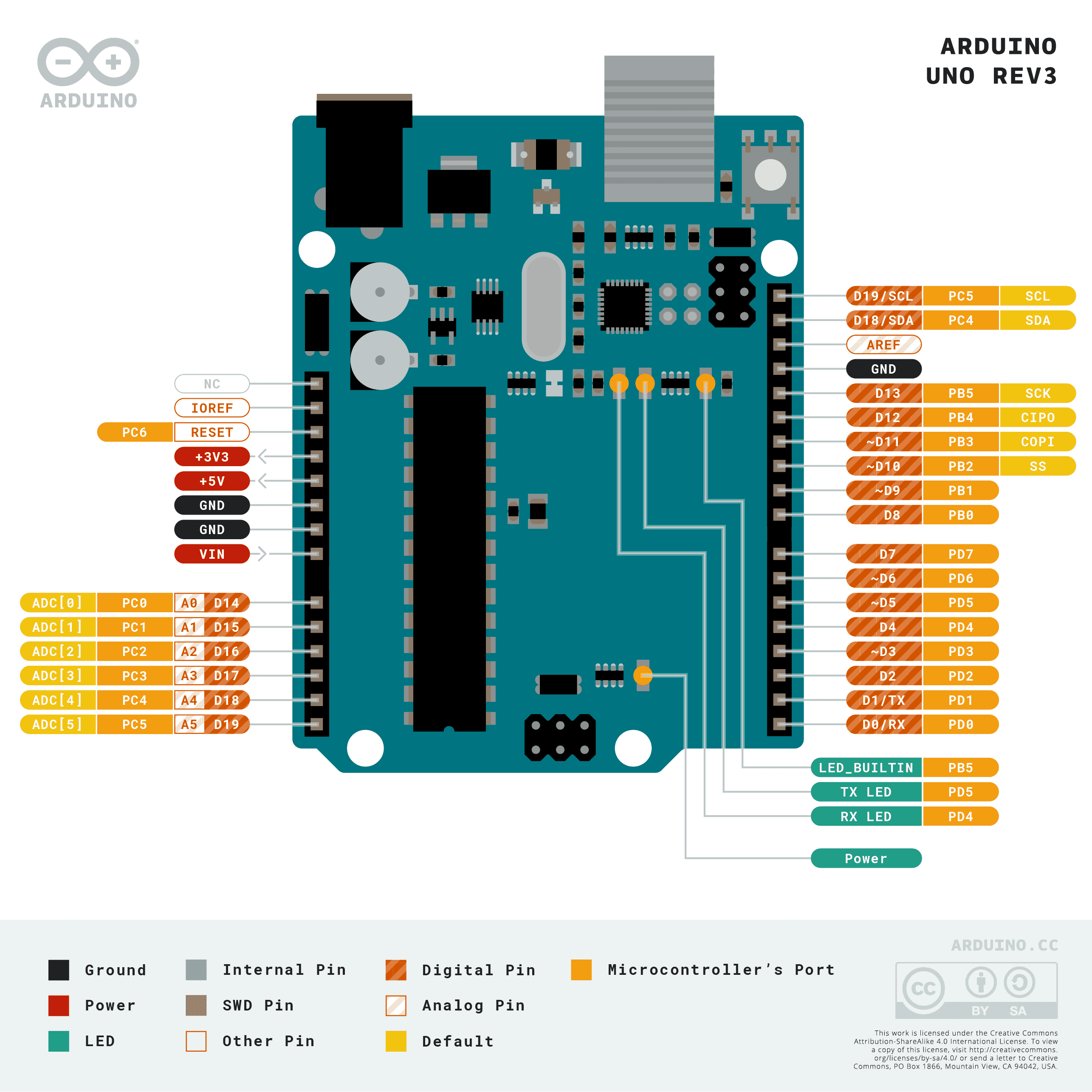
- See Arduino Uno pinout
- See Arduino Docs for GPIO / Pin Management
-
Use breadboard, wires, resistor, and a second LED. Connect it to a GPIO pin PB0 in active-low way and modify your code to blink both LEDs.
-
See this breadboard description or that one
-
See LED resistor value calculation
-
Connection of external LED in active-low way:

Note: Picture was created by Autodesk Tinkercad.
-
General connections of LEDs and push buttons in active-low and active-high way:

Note: Picture was created by EasyEDA.
-
-
On breadboard, connect two LEDs and control them by a single output pin PB0. Is it possible to get all commbinations, i.e. ON+ON, ON+OFF, OFF+ON, and OFF+OFF?
-
After completing your work, ensure that you synchronize the contents of your working folder with both the local and remote repository versions. This practice guarantees that none of your changes are lost. You can achieve this by using Source Control (Ctrl+Shift+G) in Visual Studio Code or by utilizing Git commands to add, commit, and push all local changes to your remote repository. Check GitHub web page for changes.
Help: Useful git commands are
git status- Get state of working directory and staging area.git add- Add new and modified files to the staging area.git commit- Record changes to the local repository.git push- Push changes to remote repository.git pull- Update local repository and working folder. Note that, a brief description of useful git commands can be found here and detailed description of all commands is here.## Windows Git Bash or Linux: $ git status $ git add -A $ git status $ git commit -m "Creating lab1-blink program" $ git status $ git push $ git status


-
Run SimulIDE, use online tutorials, and create a circuit with ATmega328 AVR microcontroller.
-
All circuit and control elements are available in the Components tab. Use the following components: ATmega328 (Micro > AVR > atmega > atmega328), resistor (Passive > Resistors > Resistor), LED (Outputs > Leds > Led), and GND (Sources > Ground (0 V)) and connect them as shown.

-
Right-click on the ATmega package and select Load firmware. In your project folder, find the
*.hexfile that was created by the previous compilation process. -
Right-click on the ATmega package and select Open Mcu Monitor to view internal registers and memory contents. Select Variable folder. In the Reg. column, type
DDRBon the first line andPORTBon the second. -
Click to Power Circuit button at the top of the window to simulate the project and monitor the LED status and register values. The simulation can be paused with the Pause Simulation button and stopped by pressing the Power Circuit button again.
-
You can connect a probe (Meters > Probe), an oscilloscope (Meters > Oscope), a voltmeter (Meters > Voltimeter), or a frequency meter (Meters > Frequencimeter) to output B5 and observe the signal.
-
Properties of individual components can be found/changed by right-clicking on the component and selecting Properties.

-
To verify the duration of delay function, use jumper wire and connect Channel 0 to Arduino board pin 13 (pin PB5 is connected here). Connect logic analyser to computer via USB cable.
-
Run Saleae Logic software. In Logic ver. 1 press two green arrows, set the sampling rate to 2 MS/s and the recording time to 1 second. Click the Start button to start the sampling.


-
Install the AVR development tools on your computer.
-
Modify the code from
lab1-blink_arduinoexample and build an application that will repeatedly trasnmit the stringPARISon a LED in the Morse code. Choose the duration of "dot" and "dash" so that they are visible during the simulation and/or implementation. Note that the proper Morse code timing is explained here. -
Simulate the Morse code application in SimulIDE.
-
Draw a schematic of Morse code application, i.e. connection of AVR device, two LEDs (one in active-high, second in active-low way), two resistors, and supply voltage. The image can be drawn on a computer or by hand. Always name all components, their values and pin names!
-
GitHub, Inc. Mastering Markdown
-
Tomas Fryza. Useful Git commands
-
Joshua Hibbert. Git Commands
-
Stephen C. Phillips. Morse Code Timing
-
Science Buddies. How to Use a Breadboard for Electronics and Circuits