DC5V WS2812B is not working after plugging to Dc5v #44
Comments
|
Yes, the led strip needs to receive data from RPi or some other controller. |
|
how can i assure that the strip working correctly without a controller. still i dont have a controller. how to test that is working? i ordered form the link you mentioned in your site. i want to verify it working correctly. i got the order. |
|
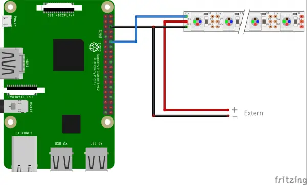
Depends. If you've got a Raspberry Pi then connect everything using the instruction and this picture, prepare your RPi and test the WS2812B by launching visualizer.py. |
if you quickly tap the data wire on ground led's will light up. |
that photo you got in 'this picture', is that how led strip is wired up for this project? |
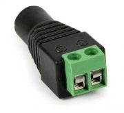
Yes. Not being skillful with wiring (and schemes like that depicted on the picture), I've been searching for more detailed steps to set things up. The trick is to put two ground jumper wires into the same "-" socket of the connector. |
the more issue i'm having is figuring out how the power wires go into the raspberry pi zero itself. also not 60/meter, but 72 so that its 1led per meter im wondering if that would work. I'll probably attempt a build in march some time when i have a evening free or so i could test it out. |
Powering the RPi seems to be the easiest part - power bank does it good.
Please no. Already failed because of similar reason - now I occasionally use that "not-so-dense" led strip for house lighting. Long story short - visualizer won't work properly with led strips other than 144 leds/meter, and also "144 strip" is the only one that can cover every single piano key - otherwise a lot of keys will be skipped.
Good luck! P.S. It is said that you can discard the external power supply as well - RPi's power can light up over 20 leds simultaneously. But that's suitable for testing purposes only: you won't be able to play piano pieces that are too dynamic/difficult and led animations will go to waste too. |
Fixing data wires won’t be too hard imo for me anyway I got loads of shrink wrap no biggie. I think I know how to make it all now will attempt in March. Also 144/meter is 2 LED’s per key, not 1. I don’t see advantage of using 2 over one as it’s just harder to power. Much harder. Have you tried 72/meter at all? (72x1.22 = 88, 88 keys on piano). This is the strip density I have used for all my other visualisers I have made with arduino and esp methods. Just a quick few questions for you as you’ve built it, is ws2812b latching issue around? As I transitioned to apa102b for the clock pin due to the latching issue as well as better colour etc, but me using ws2812b would be much easier than recoding it to work with apa102 if the latching issue does not exist. Do you use all LED’s at 50% power or max? On pre-programmed modes, I’m not sure how many there are, for each key pressed does 1 led turn on or 2? As density wise there is 2 per key. (144 x 0.22 = 172, 172/88(keys in piano) = 2) Thanks |
|
That's great then. As for 72/meter strip, can't tell much because I didn't try it indeed. Everyone who tried using it will be welcomed here Don't know this one too, alas. Judging by what I've googled apa102 is better than ws2812b but is less known and uses the whole different protocol. Regarding the LED power - it's 50%, I've ordered the "5v 6a" power supply as suggested and the strip still shines brightly enough. One led per key. The code contains specific offset function - because without it even with 144/meter strip being used, wrong leds (with inaccuracy of 1-2 leds) are getting lit in the right half of piano... presumably, as I didn't yet try to remove/edit that function. |
After connecting to Dc5v its only lighted up the first led bulb and it was green and others were not. Why is that. Does it need a controller or something to work the whole strip
The text was updated successfully, but these errors were encountered: